@moderator
Forum Replies Created
-
AuthorPosts
-
July 2, 2026 at 02:30 #27621
 ModeratorKeymaster
One of my favorite upgrades we made to Rainshadow was to replace certain portlights with opening ones – the one above the galley, the one in the head were really good choices. We also replaced the starboard portlight in the aft cabin – but that one gets used less often.
We made a posting about it on our personal blog: svrainshadow.com
Marilyn
September 26, 2025 at 18:04 #27586ModeratorKeymasterAs I understand it, the early hulls had a 4-107. Later hulls had the 4-108.
Rainshadow is hull #126 from 1974 and began with a 4-108. Not sure when the change was made.
Another difference I’ve noticed about people’s comments on engines
– Rainshadow has a Sherwood G65 raw water pump. I think it is more common that the 4-108 has a Jabsco water pump.
– Rainshadow has a front mounted heat exchanger. I’ve seen photos of other people’s Nic-38 that have the Bowman heat exchanger at the exhaust manifold.Marilyn, moderator
September 24, 2025 at 23:15 #27571ModeratorKeymasterWe still have our original Perkins 4-108. We have faced the same dilemma several times ourselves – but have always decided the opposite course. That is – find the replacement parts and keep going. Last year, we did replace our fuel injection pump with a reconditioned one – it was starting to leak at the banjo bolts. The shop rebuilt the injectors at the same time.
Our engine itself has always kept running. It’s the peripherals that have let us down. We’ve had to replace the high pressure fuel lines, fuel injection pump, fuel pickup line (make sure yours gets all the way to the bottom of the tank!), fuel shutoff cable, bleed screws, raw water pump … But everything within the block just keeps working great and so we keep feeding the beast.
I would be very curious to learn how it turned out for you replacing your engine. Are you happy with that choice? Which engine did you choose? How many other parts did you have to replace at the same time, for example, raw water cooling circuit, water lift muffler, gearbox, prop shaft and prop? Does everything need to be changed to match the power capabilities and fuel/air requirements of the new engine?
Thanks – Marilyn
September 15, 2024 at 15:49 #27503ModeratorKeymasterHi Arild – what sorts of problems are you having? We still have our TMP 12000, so we are curious about symptoms to watch out for.
This year, we had the gasket fail on the top sender unit, but we were able to repair that ourselves. When the oil pressure is low, it won’t go into gear – we like that feature as it protects the gearbox, and warned us that we should look for an oil leak.
Otherwise it seems to be running great, but we don’t really understand what symptoms might indicate impending failure.
March 21, 2024 at 19:00 #27474ModeratorKeymasterGood idea Duncan – I copied those words over to a topic that Mike started some time ago, which shows the ‘before’ photos.
Marilyn, moderator
March 21, 2024 at 18:59 #27473ModeratorKeymasterI’m copying over how Kestra now has a new headliner, where they described it in another posting. This info is from Mike, Kestra’s owner, not me –
Marilyn, moderator
*****
Condensation had brought down the edges of the ceiling, so we removed the fabric and the plastic clip trim leaving the screw fixed male runner. All ceiling mounted bits, lights etc were removed and cleaned.
A centre line was established fore and aft in the underside of the coach roof and the ceiling was set out to approximately the panel strips of the original ceiling but with a break at the centre line.
The ceiling was cut from 1mm hygena sheets used for clean rooms which is available for delivery rolled up. Three 1mx2m panels were ordered. I investigated thicker material but it is heavier and less flexible. This material is very shiny so it was covered with white non-foam backed vinyl from a yacht upholsterer and stuck on with evostik.
The panels without vinyl are set out to the centre line and the square corner of the panel establishes the line across the coach roof. A gap of approximately 10mm was left at the edges which are not square with anything. The panels are measured, marked out and scored with a sharp, knife and snapped. The panels were butt jointed and haven’t needed a joint cover.
Any holes needed are cut and then the vinyl is stuck on and folded over about 20mm. Inset from the 20mm 100mmx25mmx6mm hardwood battens are fixed on the coach roof and heavy duty Velcro is stapled to them. The other part of the Velcro is then stuck to the underside, the Velcro has its own adhesive. Finally the panel is offered up and pushed home. None has come off. We are very pleased with it.
The 6mm gap needs to be maintained because of condensation and the ply patresses used to mount lights etc which abound.
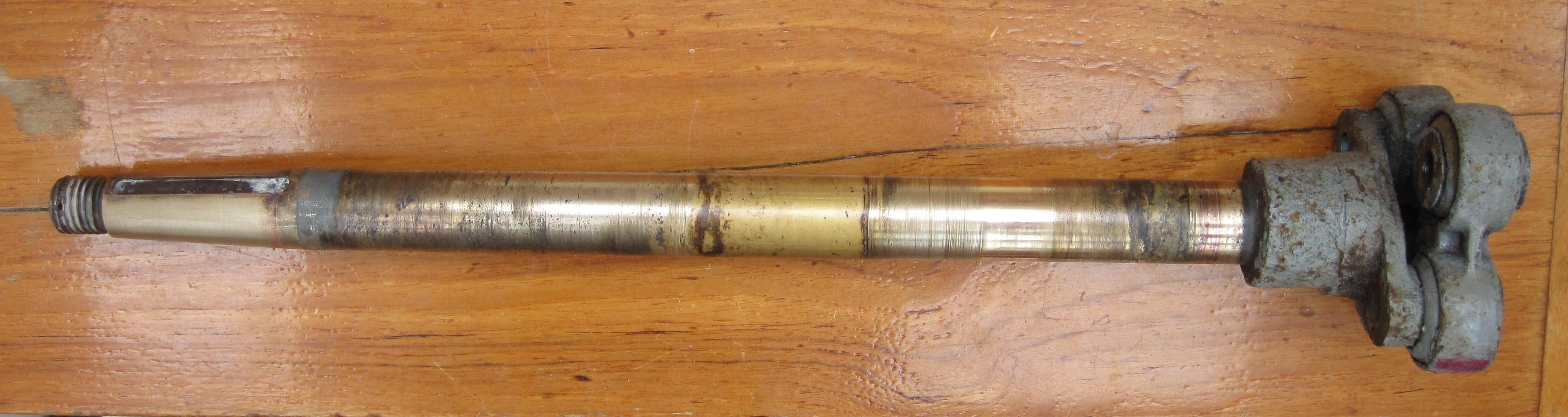
March 11, 2024 at 22:11 #27461ModeratorKeymasterBTW we assumed our shaft would need remaking, but Pete at PT Foundry said even though it had some corrosion, he thought it was still fine – given it’s such a large diameter (1 3/8″) for the prop size (16″) and engine HP (Perkins 4-108 rated 50 HP).
I’m including a picture that shows just how gnarly it looked when we had it out. Pete machined the white metal bearing to fit the diameter at the worn area, not the diameter it originally was. Yes, that made it hard to slip the bearing on, but with a little soap as lubricant and more force than expected, we got the shaft original diameter through the bearing and into the worn area were the shaft rides in the bearing.
Regarding the thumping in a following sea – that is fascinating that you hear that. I got to start a new forum thread on this….
Marilyn, moderator
March 11, 2024 at 21:53 #27460ModeratorKeymasterYes, there is a drawing for the tail shaft, dwg 124 on the C&N drawing list compiled by Jeremy Lines.
For information about buying the drawings, see this posting.
Unfortunately, I do not have permission to share them via this site.
Marilyn, moderator
March 11, 2024 at 20:16 #27458ModeratorKeymasterOur original shaft bearing was white metal, and lasted about 37 years. In 2011, we replaced it with another white metal bearing, as described on a blog. Lots of pictures on the blog, and a description of the process of removing the bearing, getting a new one made that was machined to fit our worn shaft like a glove, and getting it all back together.
Hardest part was finding someone who knew what white metal is, how to cast it and machine it to be the perfect fit, as described in the blog post.
I suspect our second white metal bearing may have worn prematurely because we didn’t clean all the growth off our prop before a month-long passage in 2016. This meant the prop may have been slightly off balanced because of the growth was not uniform on all 3 blades. Yes, we ran the engine to spin the prop and make mussel soup as we departed our slip, but when we got to the warm tropical water and dove on the prop, I was surprised to see just how much growth made the 3400nm passage with us. We measured the maximum gap between the shaft and bearing after another 3000 nm passage in 2023, it is now close to a 1mm gap.
Note, we think our bearing has worn because when we are sailing at greater than 5.3 knots in a following sea, we can hear regular thumps from the bilge area, which stops when we secure the shaft so the prop cannot spin. If the seas are on beam or forward, this does not happen. We call it our audible speed log, because it only starts when we exceed 5.3 knots. Of course, we cannot hear it when the engine is running – it’s not that loud of a thump. The fact that following seas are required suggests it has something to do with the shaft having forward pressure on it? Maybe the couplers are the problem?
The original flexible shaft couplers are discussed in this forum thread. When we had our aft shaft section removed to get out the white metal bearing, we found these couplers to be extremely flexible – as in we decided to support the intermediate shaft to protect the coupler at the gearbox since the unsupported shaft just wanted to flop into the bilge. Therefore, if the engine is even close to alignment, I find it hard to believe it could be an alignment problem.
However, if your engine mounts have loosened and shifted or worn, and now the alignment is way out, then it could setup a wobble that would wear the bearing prematurely.
Duncan, please update this thread when you reach a solution. This is a common area of concern on our forum, when owners get to thinking about it.
Good luck,
Marilyn, moderator
February 16, 2024 at 23:31 #27453ModeratorKeymasterWe’ve never had this problem, but some thoughts come to mind.
If your tracks are like ours, they are held on with screws. Sounds like you have access to your back track, can you check whether the back track is held on with little screws, and whether any are loose? Maybe screws on the side tracks have backed out a bit, making in effect a hook to hold the boltrope in place?
Our tracks on the roof are plastic, not aluminum. And I cannot really imagine our bolt rope swelling, since its all made of some sort of plastic. There is also no corrosion on ours. So it could be our setup is completely different than yours.
You might try something like a silicone spray as a lubricant, but be careful about using any lubricant that might affect your canvas. Maybe test in a small area first?
Marilyn
January 30, 2024 at 02:04 #27446ModeratorKeymasterThis boat has been sold, and her new owner has asked to join the forum.
marilyn
March 28, 2023 at 20:33 #27350ModeratorKeymasterI would check with these people. This page is a for a bowman end cap, but it doesn’t look like yours.
I have sent them photos of things I am looking for, and they have been very helpful and knowledgeable.
I’m keen to learn what you end up doing. We have the same heat exchanger, so will be subject to the same problem. We did have the heat exchanger apart about 10 years ago – I don’t recall any problems then.
Marilyn
January 18, 2023 at 09:03 #27328ModeratorKeymasterHi Duncan –
I’m not answering your question, but I want to include a link to where the PO describes how he added this feature to Czarina Blue (including photos). Topic starts with a discussion about how others have done something similar.
There is an earlier topic where this was also discussed.
Note that in the earlier discussion about Removable Forestay, Van mentions that he talked to a rigger (the late Brion Toss) about adding such a forestay, and it seems Brion did not think a running backstay was necessary with the attachment point mounted just under the cap shroud tangs.
We eventually did add a removable inner forestay as Brion Toss suggested and we have no running backstay.
Marilyn, moderator
September 24, 2022 at 23:22 #27306ModeratorKeymasterHaving just reinstalled the starboard side coach roof handrail, I can answer some of my own questions from above.
First, it was not easy to remove all the original screws as I first suggested. They were badly corroded, so each turn using a flat head screwdriver was a battle the entire thread length. The easiest way to deal with removing the bronze screws is drill off each screw head, lift off the handrail, and then turn out the screw stub using a big locking pliers.
The solid coach roof construction appears to be, starting on the outside, Gelcoat, GRP, backing plate (which creates the raised region the handrail sits on), balsa core, GRP without gelcoat. The total thickness is approximately 1.5 inches (40 mm). There is approximately 5/8″ (16 mm) layer below the backing plate that consists of balsa core plus GRP.
Aside: It may be that inside GRP layer still has the resin curing wax coating. The PO tried to paint the underside of the coach roof and the paint is peeling badly due to poor surface prep.
Our solution to reattaching the handrail – we used 1/4-20″ brass threaded inserts on the underside and 2″ 1/4-20 SS screws. Here’s how we did it.
1. From the inside, use a 3/4″ drill (20 mm) to remove the bottom GRP and balsa core, but do not drill through the backing plate. Dig out any wet balsa core (fortunately, ours was dry). The goal is to make a big plug of epoxy below the backing plate.
2. From the inside, tape over the through-hole to plug it. Then from the top side, use a syringe to fill the hole with epoxy without air bubbles. The epoxy will wick into the balsa core and lower the level of the epoxy fill- be sure to add enough epoxy to account for this balsa core wetting. The epoxy will seal the balsa from further water damage.
3. Once the epoxy is fully cured, use a 1/4″ drill to make a new through-hole in the center of the epoxy filled hole.
4. The brass inserts we used came in a kit that included the required 25/64″ clearance drill bit. We used that to drill from the bottom side up to, but not through, the embedded backing plate. We then used the SS screws from the top to drive those brass inserts in with the correct alignment until they abutted the embedded backing plate. In essence, we are using the brass inserts to increase the screw thread holding beyond just that of the (probably) corroding original backing plate, which still has good overall integrity, but maybe poor thread holding.
5. Once the brass inserts were properly threaded into place, we installed the handrail using butyl tape between the gelcoat and teak handrail. Once screwed in back into place, we put a thin layer of butyl over the screw head before we epoxied in new 1/2″ teak plugs.
The 2″ screws we used was a good length because the screw has full thread engagement in the brass insert, and only barely protrudes on the inside of the coach roof.
If we had found the backing plates and balsa core to be in terrible shape, we were going to use a new strip of hardwood on the inside of the coach roof as a new backing plate and use T-nuts driven into that wood strip to avoid having an acorn nut be a dangerous protrusion from the bottom side of the coach roof.
We’ve only done one handrail so far. In part, I am writing this down so I can remember how we did it once we get around to doing another handrail. But I hope this also helps someone else with this handrail rebed project. Since there is a balsa core, it’s important to do it before the balsa core is wet and rotting.
Marilyn
September 23, 2022 at 03:01 #27299ModeratorKeymasterI updated our progress in another posting. I’ll leave this one to be the discussion of Mathway vs. Foreman steering boxes.
September 23, 2022 at 02:58 #27298ModeratorKeymasterUpdate since my last post – we got the steering box reinstalled. Some lessons learned:
– The steering gear is held down to its mount by 4 bolts. The aft port bolt is threaded into the mount, and is shorter than the rest. It does not use a nut like the other 3 bolts, because there is not room for one.
– The steering arm and gearbox are connected by mating flanges with 4 bolt holes. These bolt holes did not line up when we had the rudder centered, and the helm set to its original “rudder centered” position and the drag link installed. This is because 1 crown wheel rotation results in 5 1/2 turns of the pinion gear, and we had rotated the crown wheel lots when it was on the workbench. We decided to set the stub-tiller so the rudder was centered, rotated the steering arm to make its flange bolt pattern match the gear box flange, and left the helm in a rotational different position. We plan to remove the wheel and see if we can get the hole in the spoke that marked “rudder centered” to be at the top again. I’m not sure if everyone’s helm has this hole in the spoke – this may have been added by the PO when he installed the monitor wind vane, which requires a pin in that spoke hole be engaged with the monitor drive wheel.
– I am delighted to say the tie rod ends I described in the other post fit well. Only caveat is that once the taper is fully seated, the cotter pin hole is completely below the tightened crown nut. But the taper fits so perfectly snug that I cannot imagine the crown nut torque is what will hold those joints together while in use.
– Once we got everything back together, we learned there is no backlash in the gearbox – but there is slop in the rudder shaft coupler! This may have been the original source of the movement, and we just did not realize it due to the poor access/visibility. How we resolve that coupler issue will be the topic of another post (once we understand what happened.)
Marilyn and Van – Rainshadow
August 24, 2022 at 22:50 #27289ModeratorKeymasterWe got our steering gear box out of the boat, similar to how Trevor said in this posting. We used a 3-jaw puller to get the ball joints and stub arms separated, as described in this post.
FYI – we don’t think we have the Mathway steering version, instead have the Foreman type. The only markings we could find was stamped in the box casting that says RB551. It was originally painted red, which has all but corroded away from the gun-metal casting.
The oddest thing is, once we got the reduction gear box home, there is no more backlash!! We are 99.9% certain that we observed on the boat when this was still installed that the backlash was all from the reduction gear box, but now there is none – turning the “input” immediately rotates the “output” – and vis-versa.
We tried to move the spindle in/out of the gear box to disengage the gears, but no movement could be seen. I don’t believe things fix themselves, but when we tried to take it apart to inspect the innards, we found the 6 screws that hold the top cover down are completely corroded in place. We tried drilling the head off one screw, and it wasn’t easy nor fully successful. They are probably 1/4-2o socket head screws, embedded into the head.
Given the concern about whether we are working on the wrong part, we may clean the reduction gear box up and install it back in the boat to see if the backlash still exists, perhaps from another source? Or maybe removing it from the boat dropped the gears back in place – for now. Certainly the steering system can apply a lot more force to the crown wheel spindle than we can on the bench. If either a bearing race is failing, the gears will separate again and the backlash will return.
Note we did find a nice functioning oil fill plug on the top cover – it takes a 7/16″ socket to remove it. We discovered the gear box oil was nearly gone, and what was left had turned to goo. So we flushed the box with a variety of solvents until we got that gunk out. Now the gears turn more smoothly – there were a few rough spots.
The Mathway manual says to refill with SAE 30 oil, but we are considering using an SAE 85W-140 API Service GL-5 designed for gear boxes. However, I just noticed that Arild said
I asked Mark at Parsons Mathway Marine what oil to use, and he recommended “SAE 30 or 15W40”
Note that to one complete rotation of the crown wheel spindle results in 5-1/2 rotations of the companion flange. In other words, we can rotate the crown wheel spindle such that we ultimately result in the rudder motion engaging a different set of crown wheel teeth against the pinion. The crown wheel only turns through about 60 degrees either way from “center”.
If anyone has any advice, we’d love to hear it.
And if anyone knows a part number for ball joints that are good replacements on either end of the drag link, that would be very helpful too. Ours seem to function, but the boot is completely gone. Seems getting the taper right is very important, and I don’t know which Land Rover part is the right one for a Nic 38!
Cheers-
Marilyn
August 24, 2022 at 22:20 #27288ModeratorKeymasterIt’s been some time since the above was posted by others, but now we are undertaking cleaning up the steering gear reduction box just before the stub tiller arm. I agree with all said above, except –
To separate the ball joint from the stub-tiller arm, use a 3-jaw puller. With the crown nut removed, you can get the jaws positioned on the stub-tiller, and then push that taper out of the stub-tiller arm with the puller. This approach offers less chance to damage gears by hammering on things.
We used a 3″ puller similar to this one. It also worked to remove the arm from the top of the gear box.
I’ll add other bits of the saga as we go to the other posting I started about backlash.
Marilyn
August 15, 2022 at 18:01 #27265ModeratorKeymasterThat’s extremely helpful Guy, thank you. Now I’m thinking ours is the Foreman type – here’s a picture of the aft gearbox still in place. Photo taken from the aft deck locker.
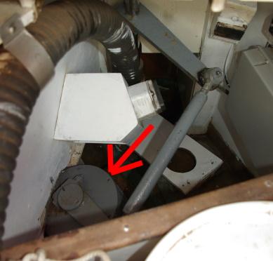
Anymore advice you can offer greatly appreciated, you seem to know a lot of about steering gear.
I’m reaching out to @jonathanc (Jonathan Carr), who wrote that FB posting, in hopes of learning more since he obviously had his all apart!
August 10, 2022 at 19:45 #27255ModeratorKeymasterWe pulled one coach roof hand hold fastener to determine size, etc. We found that after digging out the teak plug, there is a brittle layer of epoxy/varnish(??) over the screw head, making me think the screw head was disintegrating. Thankfully ours didn’t. We dug out that brittle stuff to find the fastener head with a slotted drive, and were able to easily back it out.
The original fastener is a 1/4″-20 flat head machine screw 1 3/4″ length. It’s made of bronze, and on our 1974 boat, the head and one threaded portion are quite pink but other areas look fine. The wear pattern suggested that the threaded part was being held tight in one plane about 1\8″ thick.
The next question is – what was that fastener screwed into? The deck details drawing (075.tif from the CD) say “1 1/2″ x 1″ brass plates under fore and aft handrails P & S.” Did they really embed BRASS? Drawing 74 says “aluminum” for that same note. Regardless of whether they used brass, bronze, or aluminum- given that the caulking material under the teak handhold has failed, the backing plate will have corroded as well. So simply threading in new fasteners seems highly suspect if the threads in the backing plate will crumble away.
Another concern is the coach roof drawing shows it has a balsa core, and we recall the cabin top deck is wood cored, at least where the vents are. So if water has gotten in around the hand hold fasteners, the coring surrounding the backing plate may be rotting as well.
It will be simple to add a new backing plate to the underside of the coach roof and through bolt the hand holds in place. But not so in the cabins because we still have the original headliner that is impossible to reinstall after removal. So rebedding the hand rails turns into a headliner replacement job after adding new backing plates to the underside of the deck over the fore and aft cabins. I guess we could cut little access areas in the headliner and tape them back up so we could go sailing rather than work on the boat, but that’s ugly. Another solution would be to make mating mirror image hand rails on the inside of the cabin, and through bolt outside and inside rails together with the deck between. Don’t know if that’s feasible or not, just an idea I read in Casey’s “This Old Boat” book and I thought it was a clever solution.
I’m wondering if anyone has really dug deeply into this hand rail replacement project and understands whether my concerns about corroded backing plates and rotting cores are valid. It seems so much more secure to through bolt hand rails with suitable backing plates.
Thanks in advance.
August 5, 2022 at 18:21 #27251ModeratorKeymasterDuncan’s question above is being addressed in another topic:
Any responses to this question, please reply there.
July 31, 2022 at 17:55 #27239ModeratorKeymasterAat shared many pictures of Panta Rhei II with me, and I have shared them here. She’s quite a beauty!
July 18, 2022 at 01:31 #27120ModeratorKeymasterGuy, when I look at your rudder photo posted above, it seems the rudder doesn’t have enough clearance between the aft end of keel and forward end of rudder. It’s hard to tell from the photo, but just throwing out an idea – could it be the wood rudder has swollen so badly that is jammed against the keel? Or maybe jammed at the shoe area?
For a comparison, look at the photos of our rudder on this blog post. At the bottom of that page, there is a series of rudder photos that seem to show more spacing than your photo shows. Note, these photos are from before Van rebuilt our fiberglass rudder, but that task did not change clearances.
As I recall, when I look at our rudder, I can see into the small clearance gap between the keel in rudder. On yours, can you see clearance space between the keel and rudder? How about between the rudder and lower shoe?
Just FYI, here is a photo of the keel after the rudder is removed, as well as the bottom shoe and center hinge.
Marilyn
June 12, 2022 at 20:49 #27106ModeratorKeymasterThe owners manual says:
“The anchor recess is moulded to take a 35 lb C.Q.R.”
We’ve done it, and it fits nicely. But we find the 35 lb CQR to be a little undersized.
You might consider a folding danforth type, such as the Fortress FX-23. Not that it fits nicely in the locker, but it is easy to disassemble and stow below, or it can be secured to the pushpit.
We actually carry 3 anchors, 2 plow types: Manson Supreme 35lb primary, 45 lb CQR (not 35 lb); and the Fortress FX-23, which is great in sand.
Marilyn
March 26, 2022 at 23:55 #27095ModeratorKeymasterHi Peter –
By drawing number as specified on the CD that Jeremy Lines created:
– 7 “offests for extension to hull mould”, gives dimensions for shape of hull including keel.
– 12 “sail plan” includes dimensions of masts
– 23 “Deck Plan” shows the deck layout (without interior details) and the starboard side view above waterline (keel not shown)
– 44 “Arrangement of bow pulpit” is strictly about the pulpit railing, not the bow.
– 45 “Stemhead Fitting” is strictly about the metal fitting, not the FRP bow.
I could not find drawings specifically for the bow or stern.
Hope that helps.
Marilyn, moderator
-
AuthorPosts