Welcome Back › Forums › Propulsion › Steering and Rudder › Steering/Rudder problems (and a sagging aft deck!!)
- This topic has 14 replies, 3 voices, and was last updated 3 years, 12 months ago by
 Guy H.
-
AuthorPosts
-
August 18, 2021 at 16:54 #27005
 Guy HParticipant
After some advice (as always)
The steering on Interim has always been a little heavy, but I had assumed that was normal however a couple of weeks ago it became *very* stiff.
I undid the top of the rudder gland (which was very green & dry) and squirted a load of WD40 into the end where the rudder stock come through the bushing. That freed it off to some extent but still not great
I went down this week and it is even worse 😫😫
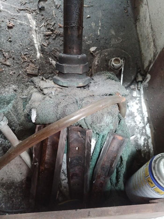
I removed the ‘gas lockers’ from either side of the mizzen and that also revealed that the aft deck has sagged and that was allowing water under the emergency rudder plate, into the box, then down the shaft and it was this that’s made the rudder gland go green.
Help!! I am feeling a little overwhelmed to be honest
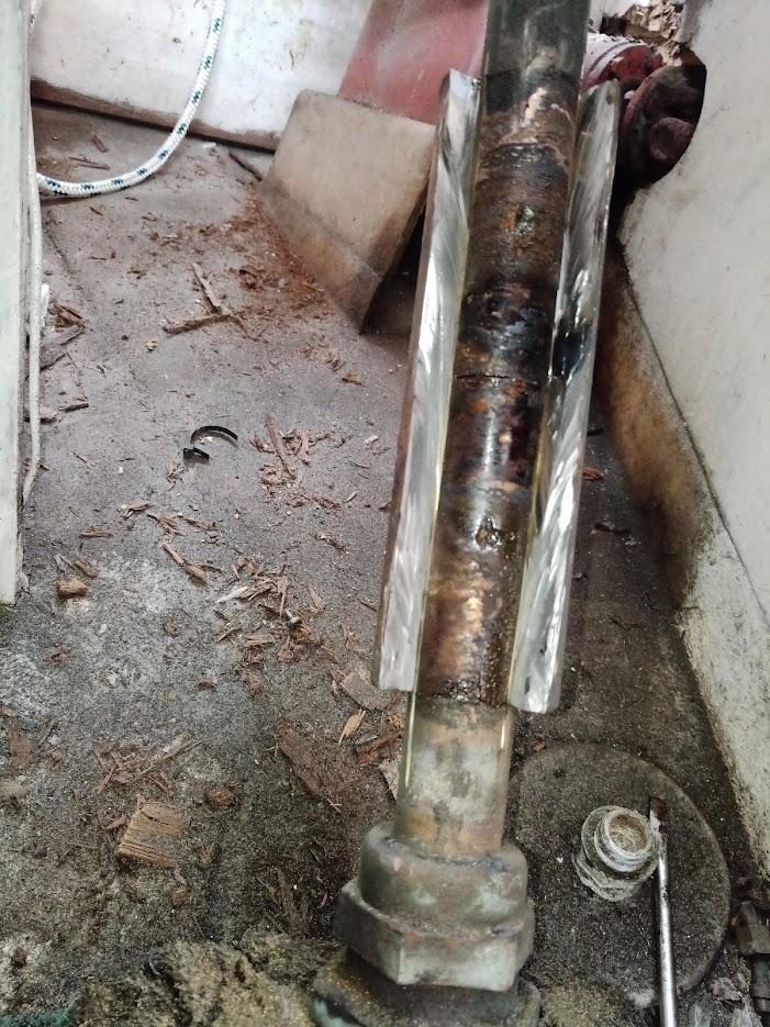
I’ve created an album of photos & a couple of videos Interim’s dodgy steering and I’ve uploaded the main video on YouTube & watching & seeing the rudder stock bend with the strain is making me feel quite ill – I hadn’t realised that was going onAugust 18, 2021 at 19:17 #27014 ModeratorKeymaster
Guy, is your boat in the water?
To isolate whether the problem is in the steering gear, or the rudder movement, have you tried mechanically disconnecting the steering gear connection at the rudder post, then use the emergency tiller to rotate the rudder? If you boat is out of the water, you can disconnect the steering gear, then go down and move the rudder by hand.
However, Van just told me his thought after watching the video is that it must be the rudder movement is jammed somehow – that the steering gear seems to be able to apply an enormous force to the rudder post, so the steering gear is fine. See Van’s good blog post on our website about when he rebuilt our rudder, if you want to know details of the rudder construction.
What could stop the rudder moving? Some ideas:
1) Something is physically in the way of the movement.
2) The bottom shoe bearing is stopping the rudder movement.
3) The hinge part is stopping the rudder movement.
4) The packing gland is seized onto the rudder post.
5) The top bearing at the deck is stopping the movement.
In other words, the rudder is held in place by 4 things, and one of them is not functioning correctly. If your boat is still in the water, I would schedule a haulout ASAP because, yes, the rudder post packing gland and where the rudder posts exits the hull is well below the water line.
Just in case you have not had a good look with Interim out of the water, there are several useful pictures of what the rudder looks like when out of the water at the top of this post and within this blog post. And this shows what the keel looks like when the rudder is removed for rebuild.
August 18, 2021 at 20:22 #27015Guy HParticipantThank you Marilyn for your reply & the links & thoughts etc
She’s still in the water at the moment.I’m going down tomorrow and will try to isolate it more – last time I was just so fed up with it I wasn’t thinking straight.
Yes, enormous forces are involved as it is bending the bronze shaft before it ‘gives’ and turns a bit. I did mention on Facebok that at least this proves that the rest of teh steering, UJs & mounts etc are in good condition … little wins
The rudder was apparently rebuilt in Iroko & sheathed in glass 5ish years ago, but it is still with the original bronze stock.
The more I look at it I think the main problem is binding in the bush under the packing gland (it’s not the ‘nut’ as that is actually unscrewed in the video.
What is leading me in that direction is the fact that I have removed the nut and there is no lubricating water coming up the bush (that the packing would normally stop leaking)So, I think my plan is to go down there tomorrow, see if I can isolate the issue, take almost all of the tension out of the mizzen lowers and see if anything moves.
In the short-term I am going to book in a haul out in October (as the prices drop by a chunk) and between now & then I am going to repair the deck under the mizzen step.
August 19, 2021 at 01:24 #27016 VanParticipant
Another comment or two: the rudder stock is not actually bending. I can’t imagine that you can bend a 1.375 inch diameter solid bronze bar as much as it looks like in the video.
Looking carefully at the video, what I see is that the top of the rudder stock (in the deck bearing) does not move. But the bottom, where it disappears from the view, does move. This looks like “bending” but I think that something else, out of sight below, is moving.
My bet is that what is happening is that the stock is “flexing” at the rudder stock coupler, which is acting like a hinge. The coupler joins the upper section of the rudder post to the lower section. The lower section is what is embedded inside the rudder. The upper section goes to the upper bearing in the aft deck. The upper section is where the lever arm that the steering mechanism needs is clamped. Each of these pieces are keyed. [The coupler is typically horribly corroded and must be cut off with a grinder. Before you do this, talk to a machinist about how to replace it. See the link https://svrainshadow.com/?p=1144 for how we did it. Or, if you are lucky, when they rebuilt the rudder they also rebuilt the coupler, and did not just use mild steel like C&N did.]
As the steering pushes the stock laterally (because the stock does not easily rotate) then the two parts of the rudder stock will angle in opposite directions, so you will end up with a shape like this: < or >. (Imagine the upper line is the upper stock, etc). The top is fixed by the deck bearing, the bottom is fixed by the stuffing box, and the coupler is where the bending happens.
Both the upper and lower parts of the rudder post must be separable in order to be able to remove the rudder when hauled out. If the post were a single piece, then you would need to drop the rudder several feet (and therefore you would either have to hold the boat that high off the ground, or dig a bloody great hole under the rudder!).
The video shows that you have full range of motion. That means the rudder physically can move (eg there is not an obstruction). That really leaves the only causes as being the four contact points for the rudder that Marilyn listed.
You should get a visual inspection of the rudder. In particular, the shoe at the bottom is made from a bronze part with a pin on it. The shoe is screwed to the bottom of the keel with several self tapping screws. The weight of the rudder should sit on this shoe. If that shoe has failed (dislodged in a grounding, or corroded away to nothing, or the screws came out), then the weight of the rudder will be on a part that is not designed to support that. (The weight is not too bad, as the rudder has some flotation, and is really not that heavy). But whatever is supporting the rudder was not designed to do that, and may be the source of the resistance.
BTW, of course look for dezincification in the rudder stock, but chances are good that it is just fine. Ours was stainless steel and had crevice corrosion so we replaced it with bronze.
Good luck!
Van
August 19, 2021 at 10:19 #27017Guy HParticipantAs the steering pushes the stock laterally (because the stock does not easily rotate) then the two parts of the rudder stock will angle in opposite directions, so you will end up with a shape like this: < or >. (Imagine the upper line is the upper stock, etc). The top is fixed by the deck bearing, the bottom is fixed by the stuffing box, and the coupler is where the bending happens.
I think you are most likely right there – in one of the other videos you can see fluid moving in & out of the interface between the coupler & the lower stock
The video shows that you have full range of motion. That means the rudder physically can move (eg there is not an obstruction). That really leaves the only causes as being the four contact points for the rudder that Marilyn listed.
Yes, that was about the only thing I could think of eliminating last time I was there. & then thought of using my camera to ‘see’ what was going on
You should get a visual inspection of the rudder. In particular, the shoe at the bottom is made from a bronze part with a pin on it. The shoe is screwed to the bottom of the keel with several self tapping screws. The weight of the rudder should sit on this shoe. If that shoe has failed (dislodged in a grounding, or corroded away to nothing, or the screws came out), then the weight of the rudder will be on a part that is not designed to support that. (The weight is not too bad, as the rudder has some flotation, and is really not that heavy). But whatever is supporting the rudder was not designed to do that, and may be the source of the resistance.
Thank you, I’ve been looking at your blog posts & now really understand all the bits (except what’s inside of the ‘gland bearing’
The ‘box’ that holds the top/deck bearing has delaminated (you can see it clearly moving at the fwd edge where the 4 bolts are) so I think I am going to concentrate on that (& the sagging deck) as I can do those in the water. A haul-out in October is much cheaper for me & I don’t think anything is going to change in those 5 weeks. If the rudder seizes completely then it’s only about 50 yards in sheltered water to the travel lift for me. I will also use those 5 weeks to run penetrating oil inside the coupler – it’s been painted nicely on the outside so i think it was at least refurbished when the rudder was done.
I’m also going to have a good look at the top bearing and probably get a new one made in acetal whilst I fix the box area.
Thanks again
July 6, 2022 at 12:39 #27110Guy HParticipantI thought I would quickly update the thread re my rudder
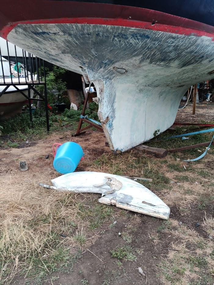
Interim is now out of the water.
The rudder-saga gets more ‘interesting’.
The rudder had jammed completely solidly since the last post and therefore she ended up on a truck being taken to a very DIY-friendly boatyard slightly closer to home (albeit still an hour each way 🙁 )P.S. to see the full-size images right-click and open in new tab or whatever and you will see the originals
The rudder seems to be jammed in the stuffing box or whatever bearing is below that.
Whilst in the water lots of salt appeared around it – it’s not leaking between the shaft and the stuffing box as that seems *very* dry (and above waterline), so it’s either around the stuffing box or it’s not from water but some other process ?? ….The PO had the rudder re-made in wood. This was then sheathed with a thin layer of glass.
The glass has been rubbed off the rudder on the fwd edge where it’s clearly been rubbing, this has led to water ingress and further damage.
I’m not even sure it was epoxy as the glass has very little adhesion to the wood and there does not seem to have been any resin impregnation as the wood is wet underneath (albeit still solid)So … now I have to try and free off the top stuffing box thing to be able to move the rudder to be able to remove the prop and the U-bracket and then drop the rudder & repair
Is there a bearing under the stuffing box does anyone know?
July 12, 2022 at 00:05 #27111VanParticipantAccording to the design drawings, there is no hidden bearing under the stuffing box.
My vague memory of reinstalling the rudder was that you just shove the shaft up the hole and it comes out the stuffing box, which you then reassemble around it, and then attach the coupler. The order of doing things matters, I had to do it twice because I forgot the parts for the stuffing box until after I had attached the coupler 🙁
Do let us know what you find when you eventually get it free.
Our stuffing box for the rudder is plastic.
Van
July 16, 2022 at 11:40 #27119Guy HParticipantthanks for your reply – I did buy the rudder drawing and could not see a bearing but wasn’t sure.
I’ve tried steam/hot water, vinegar & various penetrating oils now and they have made a small difference to the movement, but not a lot – I have about 5 degrees of movement now to port, none to stbd and none up/down.
I’m going to remove the sink so I have better access & try to get the coupler off next time with the help of a blowtorch and one of those hydraulic rams (tried without heat & no go)
The coupling is in good condition so it might work.I think I will replace the stuffing box with a Tides Marine bearing/seal here – not sure
I am trying to work out ‘worst case scenario’ of getting hold of the rudder from the outside and just forcing it ….
July 18, 2022 at 01:31 #27120ModeratorKeymasterGuy, when I look at your rudder photo posted above, it seems the rudder doesn’t have enough clearance between the aft end of keel and forward end of rudder. It’s hard to tell from the photo, but just throwing out an idea – could it be the wood rudder has swollen so badly that is jammed against the keel? Or maybe jammed at the shoe area?
For a comparison, look at the photos of our rudder on this blog post. At the bottom of that page, there is a series of rudder photos that seem to show more spacing than your photo shows. Note, these photos are from before Van rebuilt our fiberglass rudder, but that task did not change clearances.
As I recall, when I look at our rudder, I can see into the small clearance gap between the keel in rudder. On yours, can you see clearance space between the keel and rudder? How about between the rudder and lower shoe?
Just FYI, here is a photo of the keel after the rudder is removed, as well as the bottom shoe and center hinge.
Marilyn
July 18, 2022 at 17:34 #27130Guy HParticipantHi Marilyn
Yes, I think you are right as there are a couple of areas where the aft end of the keel has worn off the sheathing.

(right click on the image and open in new tab to see full-size)BUT, unfortunately, that not where it’s jammed 🙁
I have been looking at all of your post & photos & couldn’t really see one with the clearance, but I am certainly going to reshape the forward edge of the rudder – the clearance is minimal and the prop aperture is not right.
If I grab hold of the base of the rudder I can move it on the shoe so I don’t think that’s where the jam is either. There is a gap between teh rudder and the shoe so I guess the bearing is in there
I just think that it’s a buildup of salt in the stuffing box or salt and/or marine growth in the ‘tube’ down through the hull.
I will shoot a video which might throw more light either Wed or Thurs (it’s almost 40C here in the UK at the moment & we are just not setup for this heat!!)
Thanks
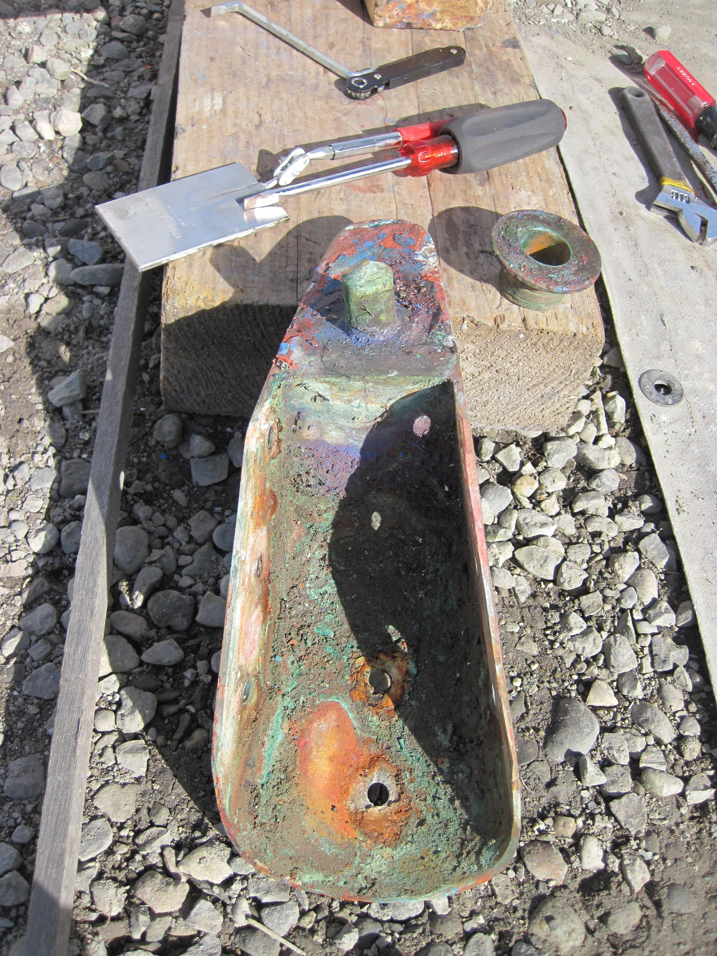
July 27, 2022 at 09:18 #27133Guy HParticipantJust to update the thread with the outcome – well it was a combination of things.
- the stock was very tight (salt buildup) in the stuffing box area
- one of the rod ends on the steering arm linkage was very tight (not stainless)
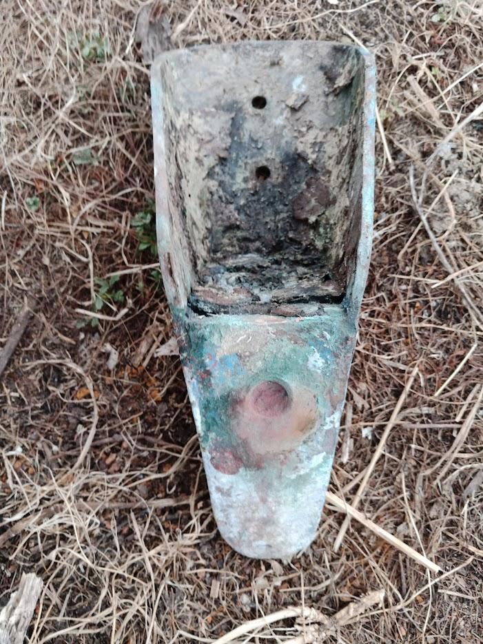
- the shoe ‘pin’ had corroded to a pink honeycomb and fallen off
So the rudder was in a very sad state
What didn’t help was where the propshaft had been ‘shoved’ aft to accomodate the rope cutters it also meant you could not remove the prop !!! gotta love the work done by some ‘professionals’ …. so out came the angle grinder (I needed a new propshaft anyway because I am changing the diesel engine)
The collar *still* would not come off after 2 cuts – it mad be made in plain steel
Another cut and managed to lever/hit the final 2 bits off
Rudder OFF!!!
Hmmmmm …..
 July 31, 2022 at 08:38 #27194VanParticipant
Yes, the collar was probably plain steel, as it was on Rainshadow. Dang, how did C&N decide to use such a poor material? It saved them a few shillings I guess. Or, maybe they realized it would be easier in 2022 to cut off a mild steel collar than a stainless one? Genius or cheap, take your pick!
In any case, you’ll need to have a new coupler made. I guess you may be able to buy one off the shelf, I don’t know.
But I do have one piece of advice. When we decided to install a new autopilot after the Neco died, I struggled to figure out how – where could you put a new tiller, attached to the rudder post, that the autopilot drive unit could use to turn the rudder? Typically, drive units want to connect to a tiller that is about 10 inches long.
Bingo! The coupler is a perfect place to put a tiller. The coupler is rigidly attached to the rudder shaft, and it must also be strong. Our coupler has six size 3/8 inch bolts holding the upper and lower parts together.
See here for a picture of the coupler (down near the end of the page):
Using these bolts, I could add a new tiller directly to the rudder post. I used 1/4 in thick Aluminum plate, about 6 inches wide to span the coupler, and attached using four of the six bolts. Our cabinet there no longer has a sink, so there is room for the tiller to swing the full distance required.
This has worked well for us. I plan to put a post on our website at svrainshadow.com, where I will have some pictures to explain. But you may be able to get the general idea anyway.
Van
July 31, 2022 at 08:50 #27195VanParticipantOh, one more thing, we drilled several small holes in the “hinge” and the first few looked great – after a very thin layer of pink dezincified bronze, the deeper metal was clean bronze. But the fourth hole was pink all the way down – very happy we tried multiple locations. We replaced the hinge.
The shoe was fine in all the test holes we made. But, it did look ugly after we removed it! Did not get a pic after it was cleaned up.
 July 31, 2022 at 09:08 #27196VanParticipant
One more idea! As you have your rudder out, I recommend that you put a 1/2 inch hole in it, in the trailing edge near the point at which it is widest (or furthest aft). In the event of a catastrophic steering failure (gear box crumbles to dust, etc) you will be able to run a line, with stopper knots through this hole, and be able to steer from the cockpit, instead of sitting topside in the rain with the cumbersome emergency rudder. See our website for a picture.
July 31, 2022 at 10:06 #27197Guy HParticipantThank you for your replies – all very useful & interesting
I will certainly think about the tiller-arm idea – it certainly adds some redundancy (I currently have a Raymarine drive unit where the old Neco one was)
From the drawings the OEM was cadmium plated steel, but I am not sure any sleeve-type couple would come off after several decades! I think shaft couplers bolted together is definitely the way to go.
My ‘hinge’ seems fine, no pinking whatsoever BUT the pin on the shoe was a pink honeycomb and had broken off. The pin seems to screw into teh shoe so I am hoping that the shoe itself is ok – I haven’t started drilling holes yet although the surface is perfect (the bits I have cleaned off so far). Both the hinge and the shoe had been liberally covered with epoxy fairing compound which probably helped protect them.


The ‘hole through the rudder’ idea is brilliant thank you! I wondered how I missed it as I had read your page countless times (I just rechecked and you have recently added it – it’s a great idea)
Thanks again
Guy -
AuthorPosts
- You must be logged in to reply to this topic.