Welcome Back › Forums › Propulsion › Engine › Aft Prop Shaft material
- This topic has 12 replies, 4 voices, and was last updated 2 years, 3 months ago by
 Moderator.
-
AuthorPosts
-
March 8, 2024 at 17:28 #27455
 Czarina BlueParticipant
My Maritex bearing from Neil at H4 marine was installed in April 2021 and already it is worn out, I have about 3mm of play if I waggle the prop underwater. I am surprised. It is possible that the shaft is not well aligned with the engine, though a mechanic signed that off when we overhauled the engine in 2022.
I have a replacement spare Maritex bearing the same size but am concerned that the shaft may be worn too much to fit it. My aft short prop shaft is some kind of marine bronze, and can be withdrawn into the boat by undoing the coupler under the aft cabin floor.
My questions are:
What kind of bronze is my aft shaft ? – I gather it would be important to stick to that metal in terms of electrolysis.
Can one weld on more material to a shaft and then skim it to fit, if there is excessive wear, or do you just replace the whole shaft section?
This problem has come on really fast and we are now in Polynesia! Once I know the metal type I can try to work out where to haul out / get a shaft repaired or replaced, if it is even possible in Tahiti…
March 8, 2024 at 18:10 #27456Czarina BlueParticipantJust got this from the FB forum:
OEM is 1 3/8″ phosphor bronze but I have been told by T Norris in the UK that’s it’s not been available in the correct quality for many years.
They have recommended 35mm duplex stainless replacement (35mm should just fit and much cheaper and easily available)March 11, 2024 at 20:16 #27458 ModeratorKeymaster
Our original shaft bearing was white metal, and lasted about 37 years. In 2011, we replaced it with another white metal bearing, as described on a blog. Lots of pictures on the blog, and a description of the process of removing the bearing, getting a new one made that was machined to fit our worn shaft like a glove, and getting it all back together.
Hardest part was finding someone who knew what white metal is, how to cast it and machine it to be the perfect fit, as described in the blog post.
I suspect our second white metal bearing may have worn prematurely because we didn’t clean all the growth off our prop before a month-long passage in 2016. This meant the prop may have been slightly off balanced because of the growth was not uniform on all 3 blades. Yes, we ran the engine to spin the prop and make mussel soup as we departed our slip, but when we got to the warm tropical water and dove on the prop, I was surprised to see just how much growth made the 3400nm passage with us. We measured the maximum gap between the shaft and bearing after another 3000 nm passage in 2023, it is now close to a 1mm gap.
Note, we think our bearing has worn because when we are sailing at greater than 5.3 knots in a following sea, we can hear regular thumps from the bilge area, which stops when we secure the shaft so the prop cannot spin. If the seas are on beam or forward, this does not happen. We call it our audible speed log, because it only starts when we exceed 5.3 knots. Of course, we cannot hear it when the engine is running – it’s not that loud of a thump. The fact that following seas are required suggests it has something to do with the shaft having forward pressure on it? Maybe the couplers are the problem?
The original flexible shaft couplers are discussed in this forum thread. When we had our aft shaft section removed to get out the white metal bearing, we found these couplers to be extremely flexible – as in we decided to support the intermediate shaft to protect the coupler at the gearbox since the unsupported shaft just wanted to flop into the bilge. Therefore, if the engine is even close to alignment, I find it hard to believe it could be an alignment problem.
However, if your engine mounts have loosened and shifted or worn, and now the alignment is way out, then it could setup a wobble that would wear the bearing prematurely.
Duncan, please update this thread when you reach a solution. This is a common area of concern on our forum, when owners get to thinking about it.
Good luck,
Marilyn, moderator
March 11, 2024 at 21:43 #27459Czarina BlueParticipantThanks Maralyn, that is really interesting. I renewed the rubbers of my flexible couplers in Colombia two years ago so they aer ina good state. God knows if they imitated the original quality of the rubber correctly. If alignment isn’t an issue (and goodness knows how you do an alignment check on a boat with a shaft made of three sections with flexible couplings, other than presenting a similar diameter long tube through the tail shaft orifice when the rudder is off, which is what we did in Saint Martin in 2021), then the only other factor I wonder about is the fact I have been using a non standard prop by Axiom, a second generation version of your one, I believe, and I wonder if that creates an oscillation or something….I am considering to try the original prop again for the next few years possibly. But I have noted exactly the same noises at the same speeds as you have, funny to read your observations! I will update as I know. A question: does there exist a CN diagram of the tail shaft that I could use to get a new SS shaft made in advance of lifting out of the water?
March 11, 2024 at 21:53 #27460ModeratorKeymasterYes, there is a drawing for the tail shaft, dwg 124 on the C&N drawing list compiled by Jeremy Lines.
For information about buying the drawings, see this posting.
Unfortunately, I do not have permission to share them via this site.
Marilyn, moderator
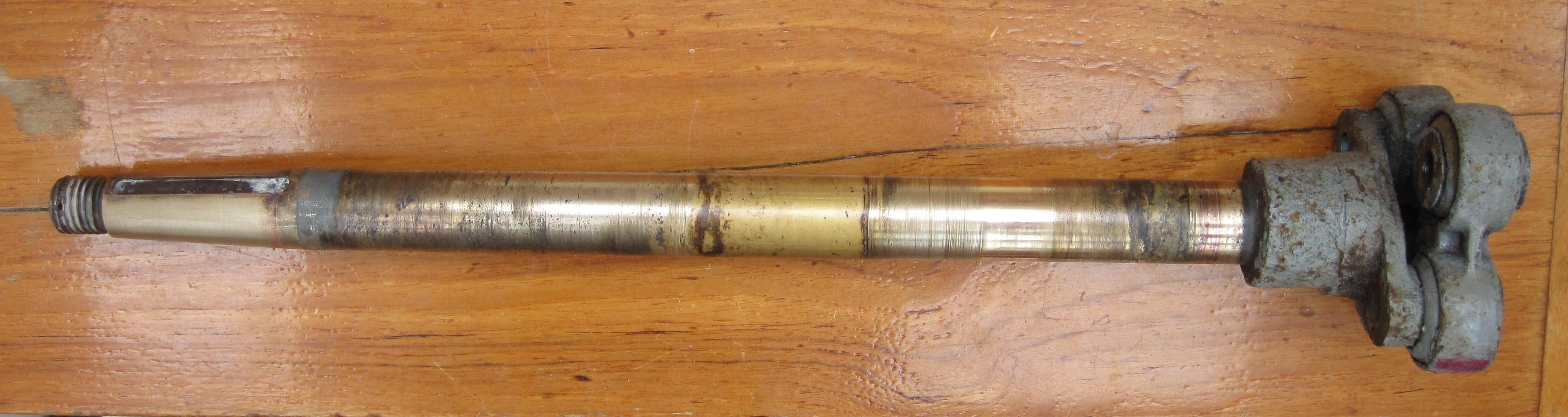
March 11, 2024 at 22:11 #27461ModeratorKeymasterBTW we assumed our shaft would need remaking, but Pete at PT Foundry said even though it had some corrosion, he thought it was still fine – given it’s such a large diameter (1 3/8″) for the prop size (16″) and engine HP (Perkins 4-108 rated 50 HP).
I’m including a picture that shows just how gnarly it looked when we had it out. Pete machined the white metal bearing to fit the diameter at the worn area, not the diameter it originally was. Yes, that made it hard to slip the bearing on, but with a little soap as lubricant and more force than expected, we got the shaft original diameter through the bearing and into the worn area were the shaft rides in the bearing.
Regarding the thumping in a following sea – that is fascinating that you hear that. I got to start a new forum thread on this….
Marilyn, moderator
March 12, 2024 at 09:38 #27466 Arild JaegerParticipant
Far Out has a 35 mm stainless steel tail shaft. When the white metal bearing was changed in 2006 it had an uneven wear and had to be machined back to a circular shape using a lathe.
The new white metal bearing goes all the way through the stern tube, except about 10 mm at the forward end, to allow grease to enter the tree grease “grooves” going all the way aft. The clearance between the actual shaft diameter and the bearing should be 0.17-0.35 mm.
Below is a copy of my e-mail dialogue with Jeremy Lines about this:
—–Opprinnelig melding—–
Fra: Jeremy Lines [mailto:jeremylines@thelasthouse.fsnet.co.uk]
Sendt: onsdag 1. mars 2006 16.06
Til: Arild Jæger
Emne: RE: Bearing clearance
Dear Arild,
I had quite forgotten that drawing, it is not listed under Nic 38 so is probably under General but I have not had a chance to look as yet. It seems to me that it is likely that it was drawn as a reference from an actual bearing. The I.D. however given as 1.375 – 1.378 seems very tight unless we were using undersize shafts. I have discussed this with Fred but unfortunately neither of us have information on white metal clearances. Fred still thinks you would be well advised to fit Thordon or Railco plastic bearings. Sorry to be so unhelpful!
Yours Jeremy.
Jeremy Lines is the Voluntary Archivist for Camper & Nicholsons.
—–Original Message—–
From: Arild Jæger [mailto:Arild.Jaeger@imarex.com]
Sent: 28 February 2006 16:52
To: Jeremy Lines
Subject: Bearing clearance
Dear Jeremy,
Would the enclosed drawing give any indication of the required clearance?
Yours Arild.
—–Opprinnelig melding—–
Fra: Jeremy Lines [mailto:jeremylines@thelasthouse.fsnet.co.uk]
Sendt: tirsdag 28. februar 2006 15.23
Til: Arild Jæger
Emne: Nic 38/10 FAR OUT
Dear Arild,
I can do no better than to send you what Fred has sent to me. His reference to John Civil was ou very experienced Foreman Fitter but I regret he retired a good many years ago and moved to Wales.
Dear Jerry
I do not like grease lubrication as it is no longer used generally for environmental reasons
Water lubrication has been used for whitemetal, but I think the wear rate is increased.
Modern synthetic bearings such as Thordon or Railko are good with water lubrication.
Rubber bearings such a Cutless or Dunlop would be fine.
However, if the client must have whitemetal, we are faced with having no recent experience with regard to clearances and practice.
We relied on John Civil to machine wm bearings when used and he would have had a book left from the previous foreman for such specialised knowledge.
The following is offered without prejudice or responsibility.
I do not have real data for whitemetal sterntube bearings, as I think the clearance required is generous by comparison to oil lubricated bearings as in an engine, which would be 0.002” for a 1” shaft running at 1000RPM, as advised by my Engineer’s Handbook
My guess would be about 0.005-0.010” per inch of diameter for a grease lubricated shaft.
With reference to the arrangement of bearings in the tube I favour a gap between the bearings and for simplicity of machining I would fit separate bearings.
The propeller bearing should be 4 times the diameter of the shaft and the forward bearing at least 2d and preferably longer.
The grease should be pumped into a gallery forward of the bearing, (and after the housing for the packing) say 10mm long and there should be generous oil grooves though the bearings.
Incidentally.
Did the stuffing box follower show signs of wear, or more significantly the small shoulder of the housing that holds the packing in place?.
Wear there would indicate that the stuffing box was acting as a bearing.
Trust this helps, but it all sounds very negative as I re read it.
Warm Regards
Fred
Jeremy Lines is the Voluntary Archivist for Camper & Nicholsons.
—–Opprinnelig melding—–
Fra: Jeremy Lines [mailto:jeremylines@thelasthouse.fsnet.co.uk]
Sendt: mandag 20. februar 2006 21.17
Til: Arild Jæger
Emne: RE: Nic 38/10 FAR OUT
Dear Arild,
Well done ! I am frankly amazed that there is only the one bearing as I had been under the impression for forty years that there were two! I see the sterngear was supplied to Halmatic by Parsons Engineering but I do not recall ever seeing the detail.
In view of what you say about the shaft diameter do you suppose that a larger metric shaft has been fitted some years ago as all our information was based on a 1.375″ shaft.
I regret I do not yet have broadband and in fact could not download your drawing but your previous photos were good and I thought I could see the aft end of the tube cut with two lugs on it to enable you to put a bar in it to twist it out.
I quite agree that to put it back basically as is, seems the right thing to do. I will chat with my friend Fred Cousins as I am sure he will be as surprised as I am.
Best regards, Jeremy.
Jeremy Lines is the Voluntary Archivist for Camper & Nicholsons.
—–Original Message—–
From: Arild Jæger [mailto:Arild.Jaeger@imarex.com]
Sent: 20 February 2006 15:21
To: Jeremy Lines
Subject: RE: Nic 38/10 FAR OUT
Dear Jeremy,
I managed to unscrew the stern tube yesterday. It was easier than I feared.
I have made a simplified drawing of the stern tube with packing which I enclose. It turned out that there is only one bearing. It also looks like the tail shaft diameter is 35.0 mm and not 34.9 mm which would correspond to 1 3/8″. It appears to have been machined down to 34.9 mm to fit into the flange at the forward end. The bronze part compressing the packing has a 36.0 mm diameter, i.e., small gap!
I have photos, but I probably need to reduce the file size before I send something to you (do you have broad-band Internet access?).
I have talked to a workshop that can help me. They suggested that they do the casting and I should find someone less expensive to to the machining…
I think I will leave the configuration intact. Since it has worked for 38 years it will probably continue to work for me. The tail shaft is only about 0.5 meter long, but i should probably have it checked so that I know it is straight.
Best regards,
Arild
—–Original Message—–
From: Jeremy Lines [mailto:jeremylines@thelasthouse.fsnet.co.uk]
Sent: 13 February 2006 19:12
To: Arild Jæger
Subject: RE: Nic 38/10 FAR OUT
Dear Arild,
All the shafting has always been 1 3/8″ and the white metal will have been cast into the fittings and then bored out. No photos as yet.
All the best, Jeremy.
Jeremy Lines is the Voluntary Archivist for Camper & Nicholsons.
—–Original Message—–
From: Arild Jæger [mailto:Arild.Jaeger@imarex.com]
Sent: 13 February 2006 13:51
To: Jeremy Lines
Subject: RE: Nic 38/10 FAR OUT
Dear Jeremy,
Thank you for talking to your friend. I did disassemble the intermediate shaft and pull in the shaft. One thing I noted was that the tailshaft diameter was 35 mm. I had thought it would be 1 1/4″, which I think it says in your documentation. Maybe a previous owner has had the same problem and decided to just increase the shaft diameter to be able to use the rest of the remaining white metal bearing?
I managed to destroy the head of one of the screws holding the forward end gland casting – and to get one out. To get to the remaining two I need a mirror to see what I am doing. It will be interesting to see whether the tube comes out!
I enclose some photos from the outside and the inside.
It sounds like your friend thinks the white metal has been moulded directly into the stern tube. Therefore it should be possible to remove it – don’t you think?
Best regards,
Arild
—–Original Message—–
From: Jeremy Lines [mailto:jeremylines@thelasthouse.fsnet.co.uk]
Sent: 13 February 2006 11:17
To: Arild Jæger
Subject: Nic 38/10 FAR OUT
Dear Arild,
I could not get hold of my old friend and engineer Fred Cousins yesterday but we have had a good chat this morning.
He is pretty sure that both white metal bearings will be integal, i.e. with no separate shell. He says it is essential to maintain two bearings to support the tail shaft.
He says obtaining the right white metal these days is very difficult and if you were to consider rubber bearings you would need to inject water forward of the forward bearing. Scoops could be fitted but as there are bound to be voids in the G.R.P. you would need to fit liner tubes and be very careful to ensure a good gel coat sealing.
We would normally take a small bleed off the engine cooling water and feed this into the greaser point with a small cock at that point. To ensure an anti-syphon effect for this pipe our standard practice was to fit a 1/8″
bleed from a high point asove the water, which exited close under the deck on the port side by the cockpit so that when running the engine you could see a small jet of water confirming that the cooling was working and would also indicate if the inlet strainer was getting fouled by a reduction in the jet.
My friends suggestion is that you should replace both these bearings with THORDON or RAILCO plastic bearings. I believe both these companies are international but he says you will no doubt have local equivalents.You just have to ensure to specify that they are the non water absorbent type.They are normally water fed but he said you might get away with greasing them but did not want to be quoted on that !
Fred has always been keen on intermediate shafts as it usually easier to pull the prop shaft forward to get it out but I did not ask if you had done that. It will be necessary to unscrew the forward end gland casting which should contain the forward bearing but it will be interesting to see if this brings the stern tube out with it.
Please keep me in touch.
Yours Jeremy.
Jeremy Lines is the Voluntary Archivist for Camper & Nicholsons.
March 12, 2024 at 15:40 #27467Czarina BlueParticipantGreat detail Arild, thank you
March 18, 2024 at 14:36 #27468Mike and Cathy Donegan
ParticipantWe replaced the white metal bearing on Kestra a year ago and had it remade to the original design.
The bearing/prop housing was removed and the old bearing taken out. The tapered prop shaft (bronze) was skimmed to remove wear irregularities caused by the bearing. The white metal bearing was recast using low zinc white metal, this involved casting an oversized plug with a central hole approximately 150mm long. This hole was then machined out to match the skimmed prop shaft, three groves machined along the inner length of the bearing and the bearing was Loctite-ed onto the shaft. The outside of the bearing was then machined to match the bearing housing tube and rear bearing housing. If I was doing it again, I would get them to extend the skimming further forward of the actual wear to include wear from the stuffing gland. It has been in a season and seems to be fine.
We have also replaced the saloon ceiling, but that is another story.
Mike Donegan
March 18, 2024 at 17:09 #27469Czarina BlueParticipantAnd who cast your white metal bearing, if I may ask?
That and a new saloon ceiling are on my list, actually, so interested to see any photos of your ceiling solution, dunkmckenzie@gmail.cois my email.
Thanks,
Duncan
March 19, 2024 at 14:19 #27470ParticipantR E Arnett, Doncaster, cast and machined the prop and the bearing.
Condensation had brought down the edges of the ceiling, so we removed the fabric and the plastic clip trim leaving the screw fixed male runner. All ceiling mounted bits, lights etc were removed and cleaned.
A centre line was established fore and aft in the underside of the coach roof and the ceiling was set out to approximately the panel strips of the original ceiling but with a break at the centre line.
The ceiling was cut from 1mm hygena sheets used for clean rooms which is available for delivery rolled up. Three 1mx2m panels were ordered. I investigated thicker material but it is heavier and less flexible. This material is very shiny so it was covered with white non-foam backed vinyl from a yacht upholsterer and stuck on with evostik.
The panels without vinyl are set out to the centre line and the square corner of the panel establishes the line across the coach roof. A gap of approximately 10mm was left at the edges which are not square with anything. The panels are measured, marked out and scored with a sharp, knife and snapped. The panels were butt jointed and haven’t needed a joint cover.
Any holes needed are cut and then the vinyl is stuck on and folded over about 20mm. Inset from the 20mm 100mmx25mmx6mm hardwood battens are fixed on the coach roof and heavy duty Velcro is stapled to them. The other part of the Velcro is then stuck to the underside, the Velcro has its own adhesive. Finally the panel is offered up and pushed home. None has come off. We are very pleased with it.
The 6mm gap needs to be maintained because of condensation and the ply patresses used to mount lights etc which abound.
I have found some photos…
March 19, 2024 at 18:01 #27471Czarina BlueParticipantThanks for Arnett reference and fascinating about the ceiling. Marilyn may want to re-locate that information to another section of the forum!
March 21, 2024 at 19:00 #27474ModeratorKeymasterGood idea Duncan – I copied those words over to a topic that Mike started some time ago, which shows the ‘before’ photos.
Marilyn, moderator
-
AuthorPosts
- You must be logged in to reply to this topic.