@arild-jaeger
Forum Replies Created
-
AuthorPosts
-
October 15, 2024 at 09:10 #27523
 Arild JaegerParticipant
Hi Marilyn,
Our gearbox works well and we haven’t had any problems with it, except that now it looks like a little seawater is leaking into the reduction gear (i.e., the rear compartment) making the oil in there look a bit like dark milk.
I asked Graham Turner of Thamesway Marine Products what he thinks is the problem. I understand that he thinks that the (moulded) aluminium between the coolant water and the oil has corroded and started leaking. I understand that this is very difficult to repair without replacing the aluminium housing of the gear.
So far the amount of seawater in the oil is very little, but I think I will have to do something about it.
Anyone who has had a similar experience?
March 12, 2024 at 09:38 #27466Arild JaegerParticipantFar Out has a 35 mm stainless steel tail shaft. When the white metal bearing was changed in 2006 it had an uneven wear and had to be machined back to a circular shape using a lathe.
The new white metal bearing goes all the way through the stern tube, except about 10 mm at the forward end, to allow grease to enter the tree grease “grooves” going all the way aft. The clearance between the actual shaft diameter and the bearing should be 0.17-0.35 mm.
Below is a copy of my e-mail dialogue with Jeremy Lines about this:
—–Opprinnelig melding—–
Fra: Jeremy Lines [mailto:jeremylines@thelasthouse.fsnet.co.uk]
Sendt: onsdag 1. mars 2006 16.06
Til: Arild Jæger
Emne: RE: Bearing clearance
Dear Arild,
I had quite forgotten that drawing, it is not listed under Nic 38 so is probably under General but I have not had a chance to look as yet. It seems to me that it is likely that it was drawn as a reference from an actual bearing. The I.D. however given as 1.375 – 1.378 seems very tight unless we were using undersize shafts. I have discussed this with Fred but unfortunately neither of us have information on white metal clearances. Fred still thinks you would be well advised to fit Thordon or Railco plastic bearings. Sorry to be so unhelpful!
Yours Jeremy.
Jeremy Lines is the Voluntary Archivist for Camper & Nicholsons.
—–Original Message—–
From: Arild Jæger [mailto:Arild.Jaeger@imarex.com]
Sent: 28 February 2006 16:52
To: Jeremy Lines
Subject: Bearing clearance
Dear Jeremy,
Would the enclosed drawing give any indication of the required clearance?
Yours Arild.
—–Opprinnelig melding—–
Fra: Jeremy Lines [mailto:jeremylines@thelasthouse.fsnet.co.uk]
Sendt: tirsdag 28. februar 2006 15.23
Til: Arild Jæger
Emne: Nic 38/10 FAR OUT
Dear Arild,
I can do no better than to send you what Fred has sent to me. His reference to John Civil was ou very experienced Foreman Fitter but I regret he retired a good many years ago and moved to Wales.
Dear Jerry
I do not like grease lubrication as it is no longer used generally for environmental reasons
Water lubrication has been used for whitemetal, but I think the wear rate is increased.
Modern synthetic bearings such as Thordon or Railko are good with water lubrication.
Rubber bearings such a Cutless or Dunlop would be fine.
However, if the client must have whitemetal, we are faced with having no recent experience with regard to clearances and practice.
We relied on John Civil to machine wm bearings when used and he would have had a book left from the previous foreman for such specialised knowledge.
The following is offered without prejudice or responsibility.
I do not have real data for whitemetal sterntube bearings, as I think the clearance required is generous by comparison to oil lubricated bearings as in an engine, which would be 0.002” for a 1” shaft running at 1000RPM, as advised by my Engineer’s Handbook
My guess would be about 0.005-0.010” per inch of diameter for a grease lubricated shaft.
With reference to the arrangement of bearings in the tube I favour a gap between the bearings and for simplicity of machining I would fit separate bearings.
The propeller bearing should be 4 times the diameter of the shaft and the forward bearing at least 2d and preferably longer.
The grease should be pumped into a gallery forward of the bearing, (and after the housing for the packing) say 10mm long and there should be generous oil grooves though the bearings.
Incidentally.
Did the stuffing box follower show signs of wear, or more significantly the small shoulder of the housing that holds the packing in place?.
Wear there would indicate that the stuffing box was acting as a bearing.
Trust this helps, but it all sounds very negative as I re read it.
Warm Regards
Fred
Jeremy Lines is the Voluntary Archivist for Camper & Nicholsons.
—–Opprinnelig melding—–
Fra: Jeremy Lines [mailto:jeremylines@thelasthouse.fsnet.co.uk]
Sendt: mandag 20. februar 2006 21.17
Til: Arild Jæger
Emne: RE: Nic 38/10 FAR OUT
Dear Arild,
Well done ! I am frankly amazed that there is only the one bearing as I had been under the impression for forty years that there were two! I see the sterngear was supplied to Halmatic by Parsons Engineering but I do not recall ever seeing the detail.
In view of what you say about the shaft diameter do you suppose that a larger metric shaft has been fitted some years ago as all our information was based on a 1.375″ shaft.
I regret I do not yet have broadband and in fact could not download your drawing but your previous photos were good and I thought I could see the aft end of the tube cut with two lugs on it to enable you to put a bar in it to twist it out.
I quite agree that to put it back basically as is, seems the right thing to do. I will chat with my friend Fred Cousins as I am sure he will be as surprised as I am.
Best regards, Jeremy.
Jeremy Lines is the Voluntary Archivist for Camper & Nicholsons.
—–Original Message—–
From: Arild Jæger [mailto:Arild.Jaeger@imarex.com]
Sent: 20 February 2006 15:21
To: Jeremy Lines
Subject: RE: Nic 38/10 FAR OUT
Dear Jeremy,
I managed to unscrew the stern tube yesterday. It was easier than I feared.
I have made a simplified drawing of the stern tube with packing which I enclose. It turned out that there is only one bearing. It also looks like the tail shaft diameter is 35.0 mm and not 34.9 mm which would correspond to 1 3/8″. It appears to have been machined down to 34.9 mm to fit into the flange at the forward end. The bronze part compressing the packing has a 36.0 mm diameter, i.e., small gap!
I have photos, but I probably need to reduce the file size before I send something to you (do you have broad-band Internet access?).
I have talked to a workshop that can help me. They suggested that they do the casting and I should find someone less expensive to to the machining…
I think I will leave the configuration intact. Since it has worked for 38 years it will probably continue to work for me. The tail shaft is only about 0.5 meter long, but i should probably have it checked so that I know it is straight.
Best regards,
Arild
—–Original Message—–
From: Jeremy Lines [mailto:jeremylines@thelasthouse.fsnet.co.uk]
Sent: 13 February 2006 19:12
To: Arild Jæger
Subject: RE: Nic 38/10 FAR OUT
Dear Arild,
All the shafting has always been 1 3/8″ and the white metal will have been cast into the fittings and then bored out. No photos as yet.
All the best, Jeremy.
Jeremy Lines is the Voluntary Archivist for Camper & Nicholsons.
—–Original Message—–
From: Arild Jæger [mailto:Arild.Jaeger@imarex.com]
Sent: 13 February 2006 13:51
To: Jeremy Lines
Subject: RE: Nic 38/10 FAR OUT
Dear Jeremy,
Thank you for talking to your friend. I did disassemble the intermediate shaft and pull in the shaft. One thing I noted was that the tailshaft diameter was 35 mm. I had thought it would be 1 1/4″, which I think it says in your documentation. Maybe a previous owner has had the same problem and decided to just increase the shaft diameter to be able to use the rest of the remaining white metal bearing?
I managed to destroy the head of one of the screws holding the forward end gland casting – and to get one out. To get to the remaining two I need a mirror to see what I am doing. It will be interesting to see whether the tube comes out!
I enclose some photos from the outside and the inside.
It sounds like your friend thinks the white metal has been moulded directly into the stern tube. Therefore it should be possible to remove it – don’t you think?
Best regards,
Arild
—–Original Message—–
From: Jeremy Lines [mailto:jeremylines@thelasthouse.fsnet.co.uk]
Sent: 13 February 2006 11:17
To: Arild Jæger
Subject: Nic 38/10 FAR OUT
Dear Arild,
I could not get hold of my old friend and engineer Fred Cousins yesterday but we have had a good chat this morning.
He is pretty sure that both white metal bearings will be integal, i.e. with no separate shell. He says it is essential to maintain two bearings to support the tail shaft.
He says obtaining the right white metal these days is very difficult and if you were to consider rubber bearings you would need to inject water forward of the forward bearing. Scoops could be fitted but as there are bound to be voids in the G.R.P. you would need to fit liner tubes and be very careful to ensure a good gel coat sealing.
We would normally take a small bleed off the engine cooling water and feed this into the greaser point with a small cock at that point. To ensure an anti-syphon effect for this pipe our standard practice was to fit a 1/8″
bleed from a high point asove the water, which exited close under the deck on the port side by the cockpit so that when running the engine you could see a small jet of water confirming that the cooling was working and would also indicate if the inlet strainer was getting fouled by a reduction in the jet.
My friends suggestion is that you should replace both these bearings with THORDON or RAILCO plastic bearings. I believe both these companies are international but he says you will no doubt have local equivalents.You just have to ensure to specify that they are the non water absorbent type.They are normally water fed but he said you might get away with greasing them but did not want to be quoted on that !
Fred has always been keen on intermediate shafts as it usually easier to pull the prop shaft forward to get it out but I did not ask if you had done that. It will be necessary to unscrew the forward end gland casting which should contain the forward bearing but it will be interesting to see if this brings the stern tube out with it.
Please keep me in touch.
Yours Jeremy.
Jeremy Lines is the Voluntary Archivist for Camper & Nicholsons.
November 20, 2021 at 00:12 #27072Arild JaegerParticipantWhite metal bearings are made from white metal alloys, which can include tin, lead, zinc, and bismuth. Of course, each white metal bearing will contain a different combination of alloys, depending on the desired strength and other requirements. White metal bearings are beneficial in that they offer an extended service life under normal operating conditions. When it comes to excess momentary overloads, these bearings also perform well. When there is an alignment or lubrication problem, the white metal bearing can compensate with greater ease than other types of bearings.
The alloys used in white metal bearings are also called Babbitt metals. These metals have a low melting point and offer very good resistance to friction. The alloys included in the bearing makeup will determine what applications the bearing is best suited to.
Many people incorrectly assume that, because white metals are considered a soft material, that they are unsuitable for the manufacture of bearings. However, the soft material incorporates hard crystals which, over time, create groove paths in the material which, in turn, provide the ideal conditions for effective lubrication of the bearing.
(Source: http://www.technoslide.com/bearing-white-metal.html)
November 20, 2021 at 00:09 #27071Arild JaegerParticipant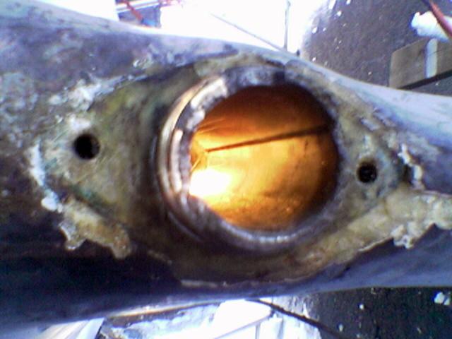 November 20, 2021 at 00:07 #27070Arild JaegerParticipant
The white metal was moulded into the stern tube. There needs to be a bit of clearance between the white metal and the tail shaft. Also pathways or grooves for the grease to pass through the bearings must be made (see photos).
November 19, 2021 at 23:20 #27069Arild JaegerParticipant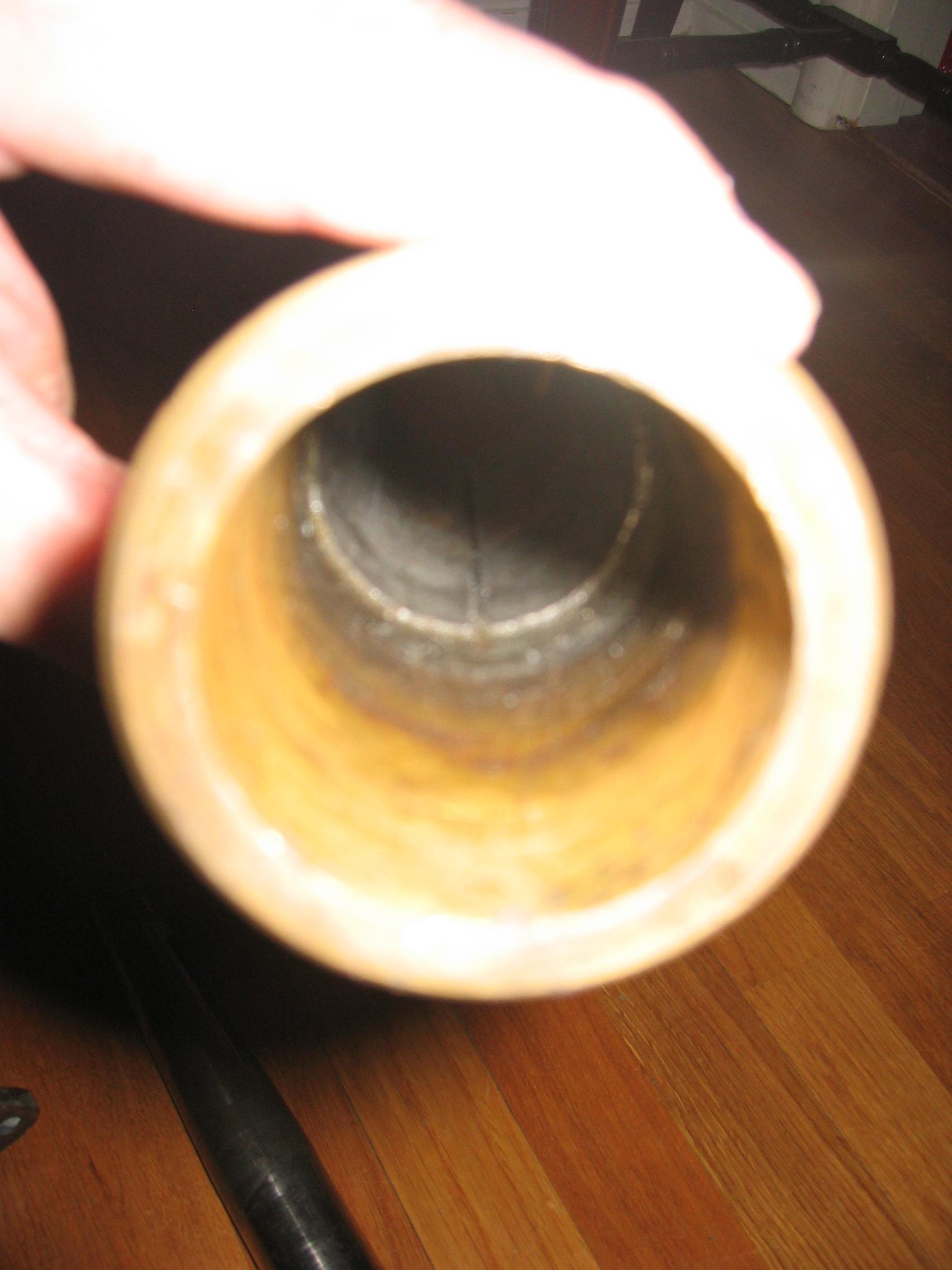 November 19, 2021 at 23:19 #27068Arild JaegerParticipant
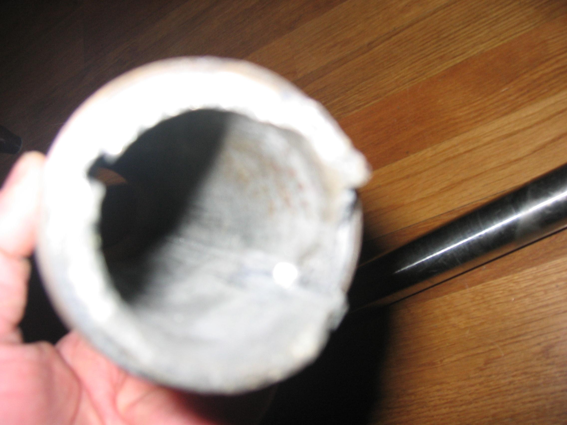 November 19, 2021 at 23:15 #27067Arild JaegerParticipant
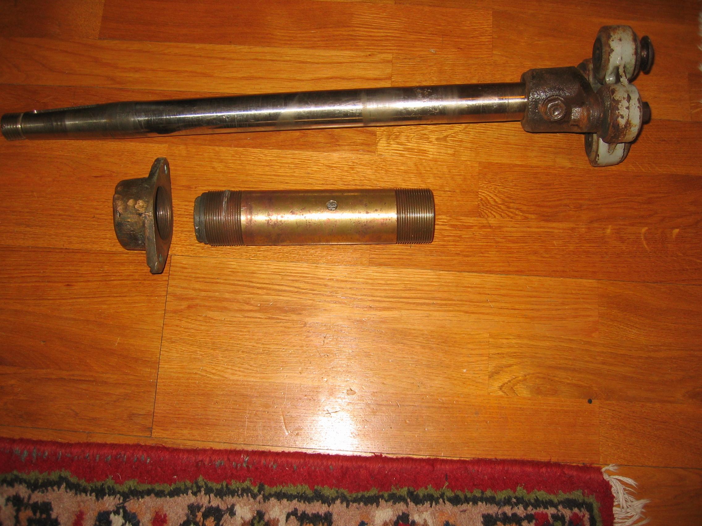 September 12, 2021 at 01:37 #27027Arild JaegerParticipant
You might want to try one of these:
https://www.marinechandlery.com/ronstan-stanchion-cap
https://www.velasailingsupply.com/ronstan-stanchion-cap-suits-d22-2mm-tube
I don’t know if they will fit, but they look similar to the original caps.
September 11, 2021 at 14:18 #27030Arild JaegerParticipantTry google’ing “Ronstan stanchion cap”.
September 26, 2019 at 11:36 #26639Arild JaegerParticipantThank you for your encouraging comments.
The weight of the mizzen mast is not to bad in itself. I can easily carry it alone. The pressure on the deck is mainly from the four shrouds/stays.
Far Out has the original configuration where the aft mainstay is held by the mizzen mast step (and led up along the mizzen mast to clear the aft cabin roof) as mentioned by Adrian. This helps to reduce the downward force – at least at the front end of the mizzen mast step .
Arild
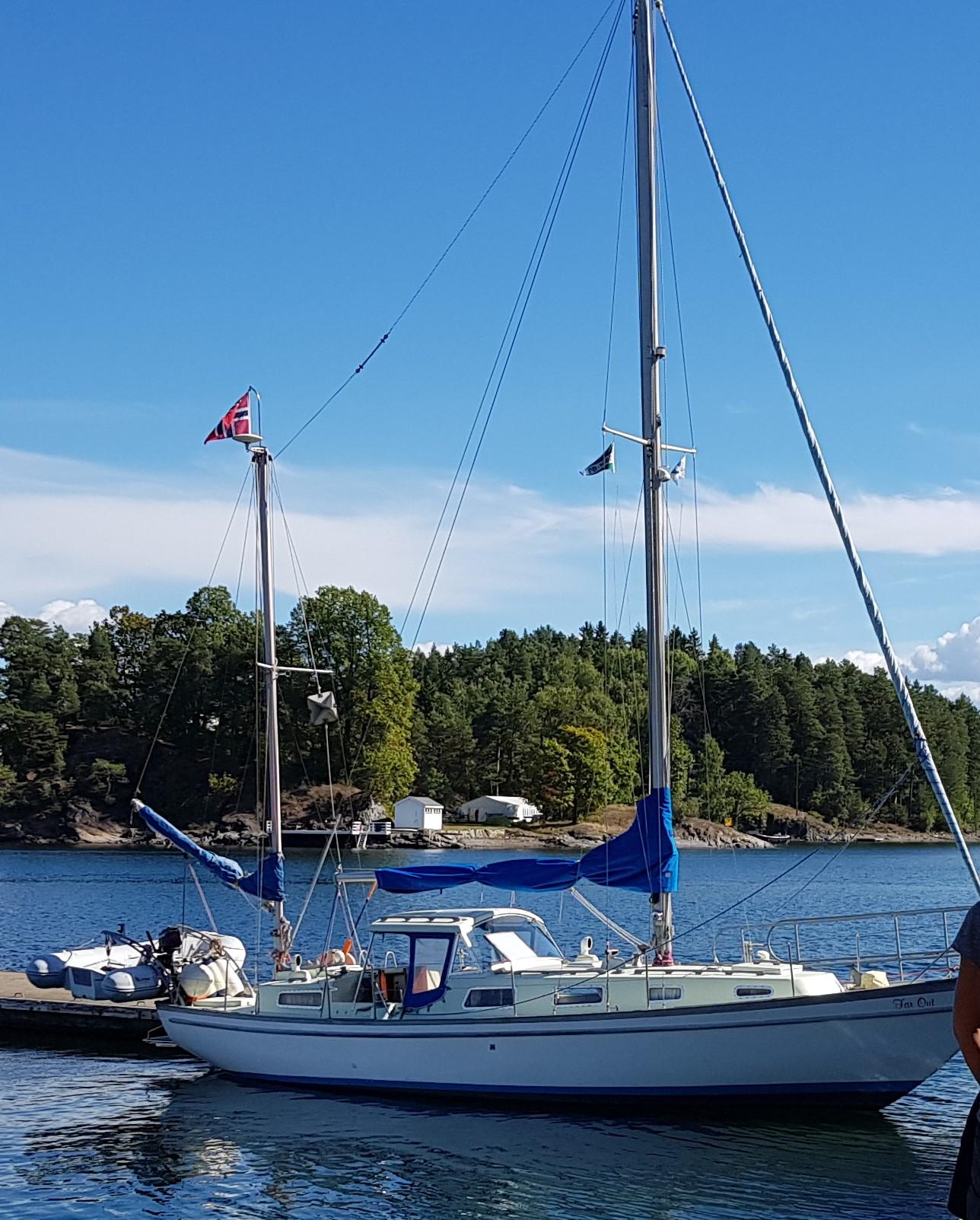
June 2, 2019 at 18:36 #26592Arild JaegerParticipant“Far Out”, Nic 38/10, flying the Norwegian ensign on top of the mizzen mast. Burgee under starboard main mast spreader.
 May 25, 2019 at 18:47 #26587Arild JaegerParticipant
Marilyn,
Thank you for your response and questions.
On the aft gearbox there is an oil fill hole on the top lid. The other gearboxes are tilted, so the sides with the oil fill holes are not horizontal. On “Far Out” only the forward gearbox (behind the steering wheel) needs to be replenished every year. After 10-15 years (since last time I checked) all the oil was still in the aft gearbox, while the lower forward gearbox had lost a little oil. In addition to checking the oil, there are several grease points which should be greased. (You can also buy U-joints which can be greased, but I decided to stay with the maintenance free U-joint when I replaced one.)
I suppose you should keep an eye on each gearbox to see how often you need to refill oil, and while you are at it you can add grease to the grease points. I was surprised when one direction of our aft U-joint was jammed at the end of the summer season. I would have thought this should have happened at the end of the winter layup, when nothing is moved for 7-8 months.
I hope to get less seawater leaking from the deck onto the U-joint going forward, so there will be less corrosion and hopefully less risk of jamming.
Arild
May 20, 2019 at 09:02 #26581Arild JaegerParticipant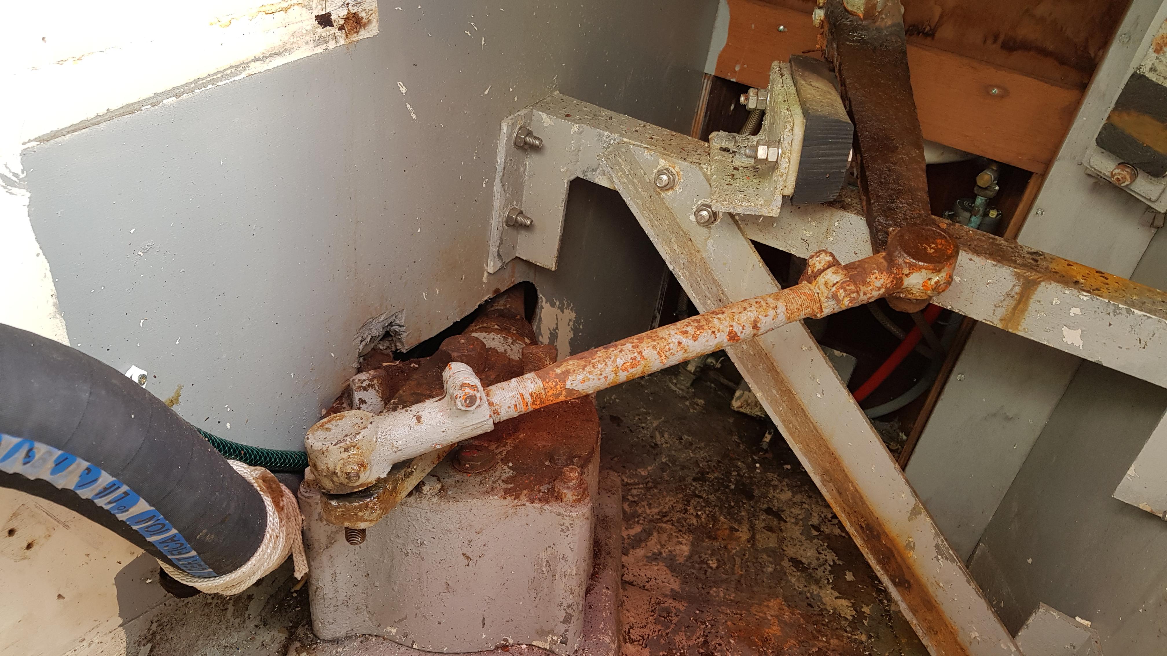
Rather rusty, before removal.
 December 14, 2018 at 11:53 #26501Arild JaegerParticipant
Dear All,
Jeremy was always very helpful to me when I asked him about our Nic 38/10.
Sadly missed.
Arild
September 18, 2018 at 08:10 #26405Arild JaegerParticipantThank you Steve,
My address is:
Arild Jaeger
Bryggetorget 15
0250 Oslo
NorwayI can be reached at
ARJAEG at ONLINE dot NOKind regards,
ArildSeptember 7, 2018 at 13:52 #26381Arild JaegerParticipantHi Steve,
We have hull number 10 from 1968 and we still use the Pinta Automatic Helmsman. Due to magnetic field disturbances, I think, it works better on some courses than other.
We also have the same radio as you, but we don’t use it as I’m not able to find any stations with good enough signals.
I would have been nice to have spare parts for the Pinta, but being based in Oslo, Norway that would probably be either too expensive or to difficult.
Kind regards,
ArildApril 25, 2014 at 21:11 #14991Arild JaegerParticipantHi Trevor,
I had the same problem and a local instrument technician just made me a new (mechanical) cable.
Kind regards,
ArildSeptember 27, 2013 at 20:18 #14311Arild JaegerParticipantJeff,
I met a friend on a Nic 35 this summer. He had just installed one panel covering the whole width. He said this didn’t work well because often half the panel would be in the shadow of the boom. Unfortunately, the panel needs to be fully illuminated by the sun to function properly. My friend has therefore decided to sell the single panel and to install one on each side of the boat instead (since the shadow would normally cover only one side).
Arild
Far Out, OsloAugust 26, 2013 at 19:08 #14051Arild JaegerParticipantAll,
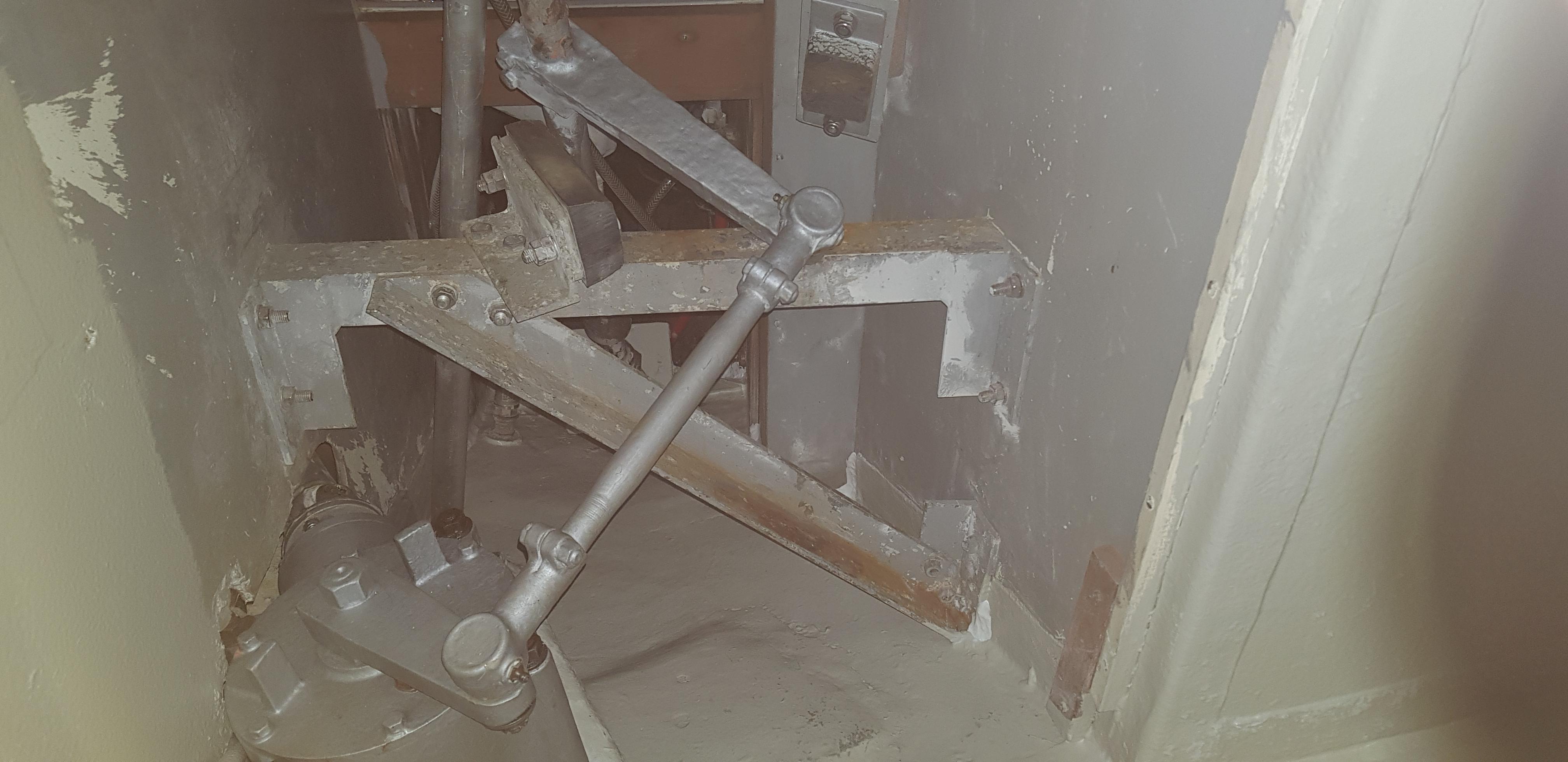
On “Far Out” I have found there is some “play” in the steering gearbox just in front of the autopilot (near the bottom of the boat in the cockpit area).
Anyone who has disassembled one of these?
Arild
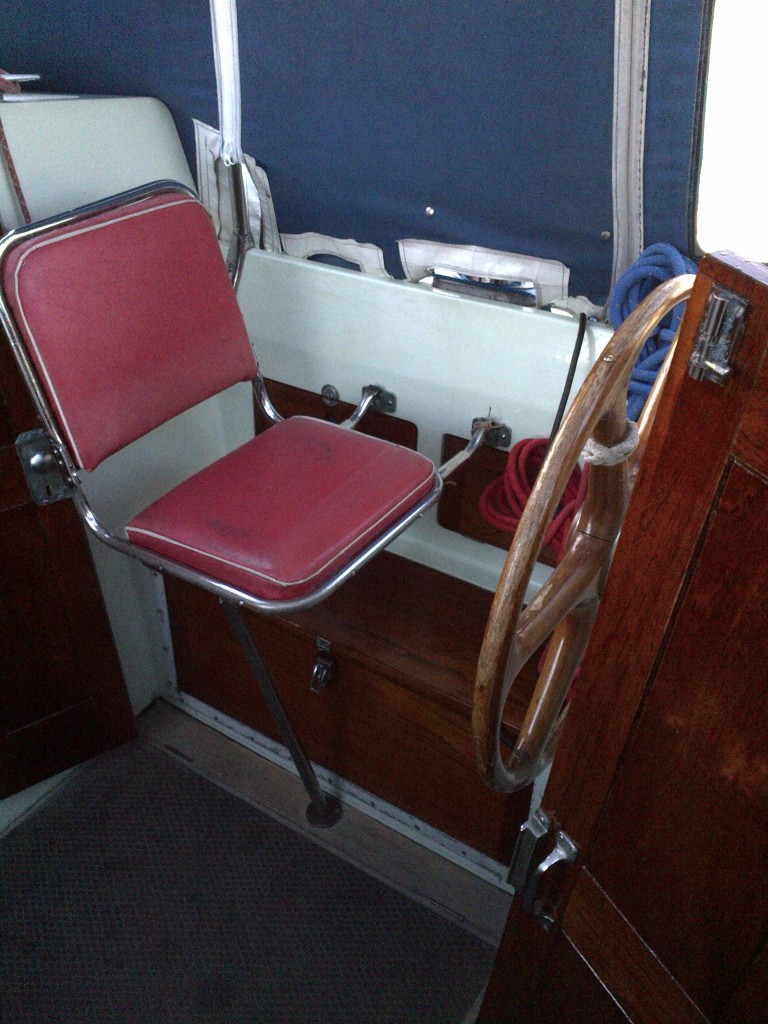
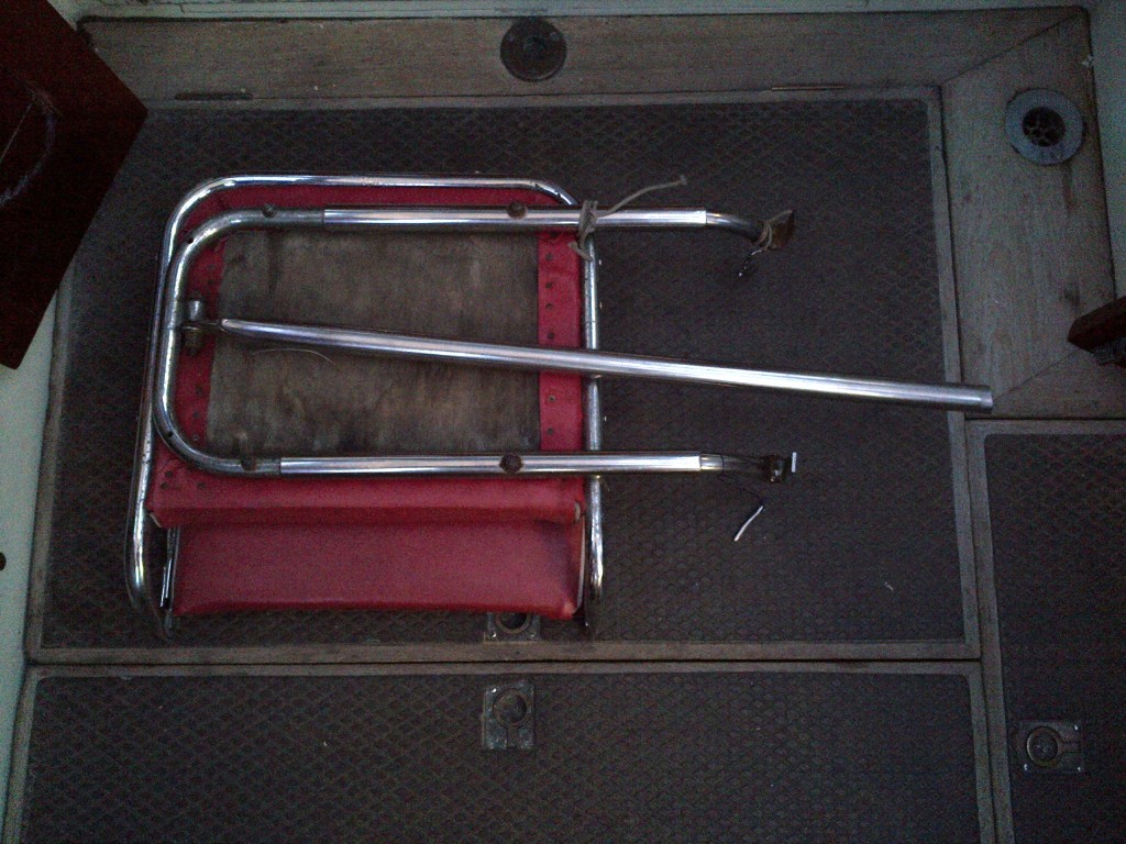
August 21, 2013 at 21:31 #6661Arild JaegerParticipantFederico asked about the cockpit seat. (Moderator merged topic into this posting)
Arild
 January 9, 2013 at 22:05 #12821Arild JaegerParticipant
Dear Ollie,
I am planning to be there on Sunday 20th. I hope to see you and your boat!
Yours Arild
Far Out, Nic 38/10November 11, 2012 at 22:55 #12501Arild JaegerParticipantMike,
I had to look up the word “fawn” in the dictionary, and if I understand correctly, the white gelcoat has become brownish. This is what had happened to my Nic 38 from 1968. I found that the gelcoat was thick enough to sand it down to its original white colour and then polish it to “good as new” colour and gloss. I used a tough 36 grit paper on an oscillating machine to get the job done – and then finer papers all the way up to 1200 paper before using a rotating rubbing machine with 1500 paste before applying wax by hand.
I realise this thread was about something else, but I couldn’t resist commenting.
Kind regards,
ArildJune 27, 2012 at 22:41 #11881Arild JaegerParticipantMike,
Before you throw the old one away, make sure you have tried to clean the spaces between the electric connectors on the rotating part of the engine (don’t know what it is called). I considered changing mine, but I found that it is a very solid construction, and that by cleaning it every second or third year, it works fine. (I actually also had to improvise to keep the static electric connectors in place. Has worked for many years now.)
Arild
June 26, 2012 at 22:37 #11841Arild JaegerParticipantHi Marilyn,
On my boat there is a rectangular hole in the bulkhead forward of the engine, which is covered by the box / step, which again can be lifted away. The hole is almost as large as the box. I hope you understand the explanation. This hole is good for access to the engine and the sea-water pump.
Arild
-
AuthorPosts