@van
Forum Replies Created
-
AuthorPosts
-
February 1, 2023 at 10:32 #27331
 VanParticipant
Just an odd thought here, what if you simply moved the top attachment up to the recommended 5% from the top, and get a longer inner stay? I see you have mechanical terminal fittings which can be reused, so you would just need to buy a new longer wire, and maybe some new cones for the fittings.
Probably a lot easier and cheaper than making two running backstays. For backstays, you need hardware, attachment points at the mast, and also on the deck. And most likely, you will not want to deal with running backstays while you are at sea.
Now, this will change the angle of the inner stay a bit. Try it, and see if it works for your sails or if the sheeting angles no longer work. If not, (or if you just think it makes sense) you can also move the deck attachment forward to keep the inner stay parallel to the forestay. There are several ways to do this that have been discussed on the forum. The way we do it on Rainshadow uses the bollard and the stem fitting, with pennants and a turnbuckle, and does not require any deck penetrations or hardware. I can send a picture of that if you want.
Van
November 29, 2022 at 05:40 #27315VanParticipantWell, after much trials and tribulations, we finally resolved the backlash issue in our steering. In doing so, as you can see above, we pulled out the gear box, flushed it with solvent, filled it with good oil, reinstalled it, and found the problem did not go away. We then realized there was slop in the rudder post – the upper part, above the coupler, could move relative to the lower part (ie the rudder) by quite a lot, I guess 5 degrees based on our earlier measurements. You had to look hard to see it, but when you did, it was obvious.
We had noticed earlier that the key in the keyway was low. Almost an inch was sticking out of the bottom. I foolishly thought that enough would be left in the upper keyway to lock the two parts together. Also, try as I might, I could not get the key to move back up. Fortunately, I have a good friend who is a machinist, and he suggested (in hindsight an obvious suggestion) to just get a little hammer, and tap the bugger back up. It worked perfectly. I used a brass hammer.
After the key was fully back in the keyway, the slop was gone. Lesson learned.
Just in case that darn key might slip down again, I clamped a stainless hose clamp around the rudder stock just below the key. It can’t move now.
Van
September 14, 2022 at 07:46 #27295VanParticipantRainshadow is 1974 also with the gold anodized spars. The original Nic 38 manual does not comment on rig tuning.
Because the mast is pretty stiff, I typically introduce some aft rake, but not much. I would guess 3-4 inches at the top of the mast based on just looking up the mast from the deck to view the bend (which I estimate is 1%). Most of the bend occurs in the upper part of the mast. The lower shrouds are used to help define where the bend happens.
I tighten the shrouds to 10% or a little more, and the stays to 15% or a little less. Then, take it for a sail and see how it behaves, and adjust as necessary. I use the ruler method for measuring tension. I like the Loos gauges but we have 5/32, 7/32 and 9/32 wires, so we need three of the gauges, that’s hundreds of dollars…..
I guess if I were you, I would defer back to the old way of doing things. A lot of rake is going to add weather helm.
The mizzen standing rigging is unusual. There was a famous rigger in Port Townsend, WA called Brion Toss, who happened to be walking by Rainshadow when she was on the hard there. I found him standing just behind the boat staring up at the mizzen with a puzzled look on his face. I struck up a conversation and we talked about the unusual arrangement of the shrouds. After a couple of minutes, he smiled and said he understood what the designers had done. He was very pleased, and asked me if I would mind if he brought around his class later so they could all look at it. (He taught rigging).
What he found interesting was how the designers used the two upper shrouds to combine to act as a forestay, and the lower shrouds to control the shape and provide much of the the tension counter to the upper shrouds, with the running backstays to finish the balance. (OK, this is my poor version of his explanation).
Van
July 31, 2022 at 09:08 #27196VanParticipantOne more idea! As you have your rudder out, I recommend that you put a 1/2 inch hole in it, in the trailing edge near the point at which it is widest (or furthest aft). In the event of a catastrophic steering failure (gear box crumbles to dust, etc) you will be able to run a line, with stopper knots through this hole, and be able to steer from the cockpit, instead of sitting topside in the rain with the cumbersome emergency rudder. See our website for a picture.
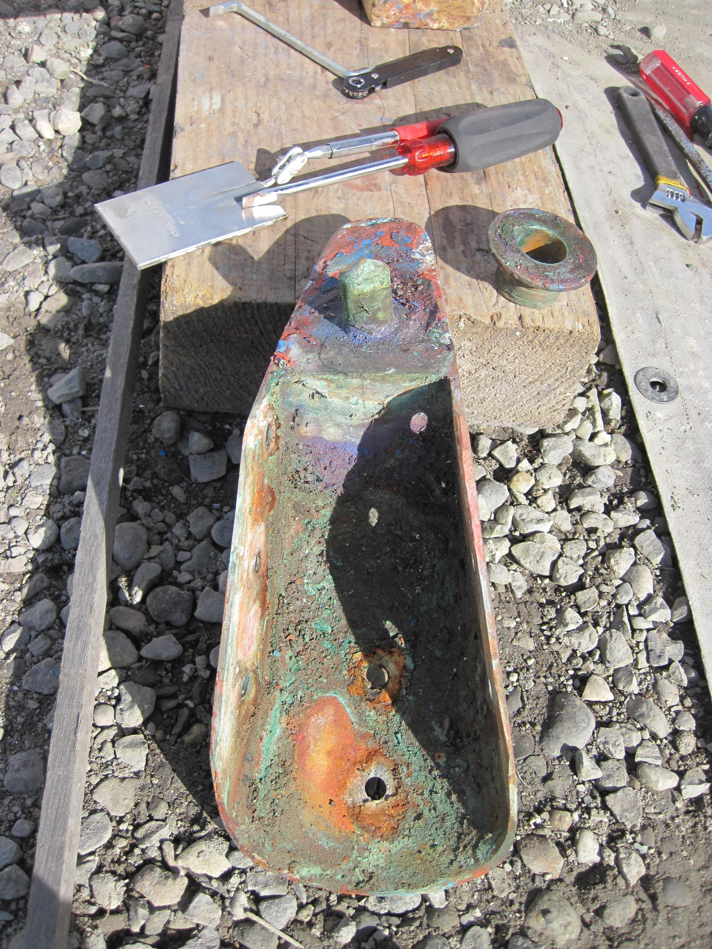
July 31, 2022 at 08:50 #27195VanParticipantOh, one more thing, we drilled several small holes in the “hinge” and the first few looked great – after a very thin layer of pink dezincified bronze, the deeper metal was clean bronze. But the fourth hole was pink all the way down – very happy we tried multiple locations. We replaced the hinge.
The shoe was fine in all the test holes we made. But, it did look ugly after we removed it! Did not get a pic after it was cleaned up.
 July 31, 2022 at 08:38 #27194VanParticipant
Yes, the collar was probably plain steel, as it was on Rainshadow. Dang, how did C&N decide to use such a poor material? It saved them a few shillings I guess. Or, maybe they realized it would be easier in 2022 to cut off a mild steel collar than a stainless one? Genius or cheap, take your pick!
In any case, you’ll need to have a new coupler made. I guess you may be able to buy one off the shelf, I don’t know.
But I do have one piece of advice. When we decided to install a new autopilot after the Neco died, I struggled to figure out how – where could you put a new tiller, attached to the rudder post, that the autopilot drive unit could use to turn the rudder? Typically, drive units want to connect to a tiller that is about 10 inches long.
Bingo! The coupler is a perfect place to put a tiller. The coupler is rigidly attached to the rudder shaft, and it must also be strong. Our coupler has six size 3/8 inch bolts holding the upper and lower parts together.
See here for a picture of the coupler (down near the end of the page):
Using these bolts, I could add a new tiller directly to the rudder post. I used 1/4 in thick Aluminum plate, about 6 inches wide to span the coupler, and attached using four of the six bolts. Our cabinet there no longer has a sink, so there is room for the tiller to swing the full distance required.
This has worked well for us. I plan to put a post on our website at svrainshadow.com, where I will have some pictures to explain. But you may be able to get the general idea anyway.
Van
July 12, 2022 at 00:05 #27111VanParticipantAccording to the design drawings, there is no hidden bearing under the stuffing box.
My vague memory of reinstalling the rudder was that you just shove the shaft up the hole and it comes out the stuffing box, which you then reassemble around it, and then attach the coupler. The order of doing things matters, I had to do it twice because I forgot the parts for the stuffing box until after I had attached the coupler 🙁
Do let us know what you find when you eventually get it free.
Our stuffing box for the rudder is plastic.
Van
August 19, 2021 at 01:24 #27016VanParticipantAnother comment or two: the rudder stock is not actually bending. I can’t imagine that you can bend a 1.375 inch diameter solid bronze bar as much as it looks like in the video.
Looking carefully at the video, what I see is that the top of the rudder stock (in the deck bearing) does not move. But the bottom, where it disappears from the view, does move. This looks like “bending” but I think that something else, out of sight below, is moving.
My bet is that what is happening is that the stock is “flexing” at the rudder stock coupler, which is acting like a hinge. The coupler joins the upper section of the rudder post to the lower section. The lower section is what is embedded inside the rudder. The upper section goes to the upper bearing in the aft deck. The upper section is where the lever arm that the steering mechanism needs is clamped. Each of these pieces are keyed. [The coupler is typically horribly corroded and must be cut off with a grinder. Before you do this, talk to a machinist about how to replace it. See the link https://svrainshadow.com/?p=1144 for how we did it. Or, if you are lucky, when they rebuilt the rudder they also rebuilt the coupler, and did not just use mild steel like C&N did.]
As the steering pushes the stock laterally (because the stock does not easily rotate) then the two parts of the rudder stock will angle in opposite directions, so you will end up with a shape like this: < or >. (Imagine the upper line is the upper stock, etc). The top is fixed by the deck bearing, the bottom is fixed by the stuffing box, and the coupler is where the bending happens.
Both the upper and lower parts of the rudder post must be separable in order to be able to remove the rudder when hauled out. If the post were a single piece, then you would need to drop the rudder several feet (and therefore you would either have to hold the boat that high off the ground, or dig a bloody great hole under the rudder!).
The video shows that you have full range of motion. That means the rudder physically can move (eg there is not an obstruction). That really leaves the only causes as being the four contact points for the rudder that Marilyn listed.
You should get a visual inspection of the rudder. In particular, the shoe at the bottom is made from a bronze part with a pin on it. The shoe is screwed to the bottom of the keel with several self tapping screws. The weight of the rudder should sit on this shoe. If that shoe has failed (dislodged in a grounding, or corroded away to nothing, or the screws came out), then the weight of the rudder will be on a part that is not designed to support that. (The weight is not too bad, as the rudder has some flotation, and is really not that heavy). But whatever is supporting the rudder was not designed to do that, and may be the source of the resistance.
BTW, of course look for dezincification in the rudder stock, but chances are good that it is just fine. Ours was stainless steel and had crevice corrosion so we replaced it with bronze.
Good luck!
Van
June 10, 2021 at 02:01 #26971VanParticipantOh, by the way, that rectangular slot in the boom can make the boom act like a flute as the wind freshes, and you get to hear this rather beautiful mournful whistling. As the wind speed and direction fluctuates, the pitch varies in a random manner. We like to call it the sound of the ghosts of drunken English sailors inhabiting our boat, and they often come out to sing when Rainshadow is flying into the wind on a starboard tack.
June 10, 2021 at 01:48 #26970VanParticipantWe have the original boom too. Removing any of the fasteners is really hard.
They are all corroded in place (stainless versus aluminum). Some had corroded so badly there was no aluminum left in the thread and the screws could just fall out (which a couple did).
So, removing the boom end cap may be a challenge!
One last thing, with the internal outhaul, it’s important that any fasteners in the sides of the boom are kept short. The Previous Owner installed some fittings and the shipwrights used self tapping screws. Horrible idea. Snags the outhaul.
June 10, 2021 at 01:41 #26969VanParticipantHi Guy, Welcome to the forum.
I’m glad to hear you could get the stuck gooseneck loose.
So my thoughts:
I can’t quite tell from your photo if your boom is still fitted with the roller reefing. Ken and Jan’s boom is not. Have a look at the first photo on this page: https://svrainshadow.com/?p=983 Just forward of the aluminum boom end where the sail tack is shackled, at the bottom of the black part you can see a hole that a winch bit fits into. That’s the roller furler. I guess this was trendy back in the 70s.
All sailmakers I talked to strongly advised against using the boom as a roller furler. So, we had a loose footed main made, which is slab reefed in the normal manner, using lazy jacks.
The tack is shackled to the hole on the top of the plate (like your photo after you replaced the cord). Along the luff of our sail are three cringles. The lowest cringle is about 12 inches above the gooseneck. I had the sail maker add that in case I needed to use the downhaul to tighten the luff. I rarely need it. The upper two cringles are for reefing.
So to answer your question: yes, a direct connection is possible, and you will want that ability anyway for reefing.
The downhaul is shown in Ken and Jan’s photo – it’s the vertical rope which they are correctly replacing with a block and tackle. Our has 3:1 purchase and is adequate. The top block is attached to a reefing hook, so I can stick it on any of the cringles. In fact, each cringle has a “dog bone” through it (a short piece of webbing with a ring at each end, on either side of the sail cringle. This makes it easier to attach the reefing hook (and I actually use a snap shackle not a reefing hook).
Regarding the force acting on the split pin, I do not think that the pin is the load bearing surface. If you look, the boom is resting upon the slider that fits into the mast. The clevis pin the is the hinge that allows horizontal movement, and is not load bearing in a vertical direction, only horizontal. So the split pin should not carry any load.
While we are talking about it, pay close attention to the hex head bolt just aft of the slider, that provides vertical freedom of motion. On our crossing from Seattle to Hilo, our crew discovered that the nut had worked its way off and the bolt was simply held in by luck and a bit of friction, and had already started working its way out. Scary! Crew got extra grog that night.
The rectangular hole on the starboard side is for the outhaul, which is internal to the boom. Check the link above for a full description of the outhaul.
Van
April 11, 2021 at 22:26 #26903VanParticipantWe are pretty happy with the way we did it on Rainshadow, which was to build a small cabinet up above the nav table. You can see it in the photo in my earlier comment. It is about 30cm tall and 15 cm deep, and in two sections.
The upper section contains three instruments that face into the cockpit through the bulkhead (Fishfinder/Depthsounder, Speed Thru Water, and Wind (latter two are Datamarine, quite old but working). It also contains the AIS box, and a data multiplexer that links the NMEA 0183 instruments to the NMEA 2000 network. So, it’s crowded up there, especially with the wiring necessary for all that.
The lower section has the main circuit breaker panel, and also room for a solar controller.
The BIG mistake I made was that I did not provide a large enough conduit for the wiring to get down to the main wiring area behind the original breaker box.
It’s not nearly large enough as over the years we have added more and more stuff (like the N2K network, additional transducer cables, AIS, USB…..). Worst, most of these cables have sizeable connectors, which barely pass through the remaining space.
Extending the cabinet all the way down like you are proposing for Rhapsode seems like a great idea, because you will have lots more room for wires and devices. Just make sure 8cm is deep enough.
Oh, and it is also really easy to drill through the bulkhead into the cockpit by accident…..
Van
October 13, 2020 at 10:51 #26774VanParticipantRoger, what model Gaurhauer did you use?
October 5, 2020 at 23:46 #26752VanParticipantOn Rainshadow we use a Monitor – a very old one from circa 1986. Scanmar, the manufacturer has been super helpful. We gave them the serial number and they knew all its history, and told us what upgrades we should do (and how to do it ourselves).
We used the Monitor a lot on our pacific crossing from Seattle to Hilo, Hawaii. There were two problems.
Firstly, the control lines I set it up with that ran from the Monitor to the wheel, were too weak and too thin (I was using dyneema, but not large enough). They had worked just fine in the Pacific Northwest, but the real ocean showed us who was boss…… They were too weak, meaning that there was more stretch than there should have been making the Monitor less responsive, and secondly, we twice had the lines chafe through even though I went to great lengths to protect it from that. Chafing through at 02:00 in strong winds and rough seas was not very pleasant, as we had to hand steer until light.
Secondly, the Monitor had a hard time steering downwind, in 15 knot winds, with large following seas (10-20 feet). We were trying to head as close down wind as possible, which perhaps was a mistake. What we found was that the following seas would make Rainshadow yaw a large amount, and the Monitor was not fast enough, nor strong enough, to return the boat to the correct direction quickly. Partly the problem was the wind was not strong enough, and partly the seas were really swinging us around. It was unpleasant, and we would often try to hand steer instead (by day 20, this was pretty hard).
I don’t know if any wind vane can steer downwind with such large following seas.
Afterwards, I talked to Scanmar and I bought their control lines – specifically designed for center cockpits, they are dyneema with a polyester outer braid. In the limited sailing we have been able to do since our crossing, the lines appear to work very well. No stretch.
Finally, we are looking to buy a Pelagic autopilot, which is a clever little “tiller pilot” sort of device, that instead of attaching to a tiller, attaches to the Monitor in place of the vane. It steers a magnetic course, and uses very little power. Pelagic are now sold by Scanmar. A friend of mine used one on a SF to Honolulu single-handed crossing, and he raved to me about it, and completely sold me on the idea. So I think one is in our future…..
Van
October 5, 2020 at 23:20 #26751VanParticipantOur prop shaft has a brush (carbon, just like the brushes in an electrical motor) that is in contact with the prop shaft just forward of the stern tube. The brush is wired to the through bolt attached to the primary external zinc. I (try) to remember to keep that area of the shaft clean to ensure a good electrical connection. I have no way of knowing if it is doing a good job!
Our primary zinc is an approx 12″ x 1.5″ x 1″ rectangle that is bolted (2 bolts) to the starboard side about level with the prop, and about 1 foot forward of the prop. This sits in a recess in the hull so that it is not really protruding very much. We are moored in brackish water, more fresh than salt, and so we don’t seem to use zincs very fast.
I don’t recall if on our boat, the castle nut that holds the prop on the shaft leaves enough room for a zinc. I don’t think so. But it seems like a very good idea.
At dock, we also deploy a “guppy”, which is a piece of zinc, on a copper wire that is wired to the ship’s bonding system, and dropped down into the water. It does decay away, we replace it about every year.
Van
October 5, 2020 at 20:31 #26750VanParticipantWe used the numbers from Jeremy. We built a Jordan drogue using the 6,700 kg design, which means 107 cones, more or less. I think we used a few more cones than that. It would be quite reasonable for you to use the next size up.
The design from Jordan is not meant to be exact, and includes a generous safety factor. The key is to make sure that the weakest link matches the design goals, which is dependent upon displacement. The displacement determines what the maximum load during a breaking wave event is – in the case of our Nic 38, I took that as 10,000 lbs, but in fact, all the components I used are rated quite a bit higher than that.
The weakest link will not be the length or number of cones, it will be the shackles, chain plates/backing plates, and ultimately the strength of the fiberglass where you mount the chain plates. As you can see from his design, doubling the boat displacement from 10,000 lbs to 20,000 lbs did not make a big difference in the length or number of cones in the drogue – from 100 to 116.
FWIW, we used dyneema lines for the bridle and leader because they do not absorb water, small and easy to handle for their strength, and are easy to splice. Elasticity of the bridle and leader is not important because the drag of the drogue does not create “shock loads”, but instead acts as a shock absorber. We used closed thimbles at all the line ends, and used over-sized soft shackles everywhere except at the chain plate, where we used shackles with 4.5T working load limit.
We are just now getting ready to install the chain plates on the aft topsides, a few inches under the toe rail.
Good luck!
Van
April 28, 2020 at 08:09 #26692VanParticipantFWIW, the old Lucas starter was a direct drive unit, and the new one is geared, which means it uses less current (so they say). It’s made by IMI and is their model 303. The starter/alternator chap waxed lyrical about how incredibly reliable these starters are. I hope he’s right, it cost almost $500. To rebuild the old one was going to be about $250, and if we’d bought a new direct drive, it would have been about $375.
Because of the experience of having the solenoid stick (and reading of other people’s experiences with the ignition switch sticking), next to the key I added a bright little red LED light that lights up when ever the solenoid is engaged. So, if the key sticks, or if the solenoid sticks, that little light will warn the crew that the starter motor is still running.
I also replaced the ignition switch with a much better one.
March 26, 2020 at 05:26 #26683VanParticipantThe shop was right, they fixed it and now it works. The problem was that the new starter uses a smaller diameter pinion gear, and to deal with the smaller diameter, they have to shift the center of the starter motor towards the ring gear (flywheel) by about 1/8th, or maybe 3/16ths of an inch. What this means, is that the thing is not rotationally symmetric. And the spacer they had installed was 180 degrees out of place. So, once they had rotated it, it installed easily and started the motor just fine.
FYI, it is an IMI-303, which is designed to fit Perkins 4-108 engines.
March 24, 2020 at 08:45 #26682VanParticipantFunny to be sitting here in Hawaii, with a state-mandated, COVID-19 lock-down due in 25 hours, and re-reading a bunch of old Nic 38 postings.
Rainshadow is currently in Hilo, but sans starter motor – we burned that out a couple of weeks ago, and the starter motor shop has one for me, which I plan to pick up, and install, in the 25 hours I have left!
I already tried installing it last week, but it didn’t work – the pinion gear did not engage the ring gear (flywheel). But the shop tells me they know what the problem was, and tomorrow I am going to go in to try again.
I’ll probably have plenty of time to write up a description on our svrainshadow.com web site. The new starter is a gear driven thing made by IMI. Supposed to be immensely reliable. We will see!
Van
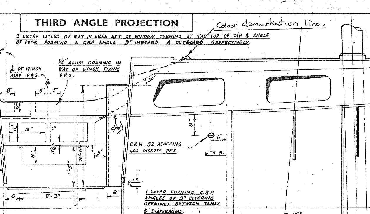
July 1, 2019 at 21:43 #26613VanParticipantJeremy Lines produced a CD of Nic 38 engineering drawings. If you look on that at file 074.tif, you can see a marking for the hole. See below. There may be more instances of the beaching legs on other drawings. It’s further forward than I expected. I don’t know anything about how it was made or used, but it would be interesting to know!
To get the CD, see this topic:
Good luck!
June 17, 2019 at 04:41 #26607VanParticipantThanks Arild, this is interesting. Nice idea to put in that support strut.
I had no idea that the deck was so dependent upon the small (it seems) plywood beam. Almost makes me think I should add aluminum supports like you did, but before it breaks.
There are a surprising number of shrouds for this mast, and the downward pressure is of course cumulative.
I set the 5/32″ shrouds to 300# and the 7/32 to 500# (about 10% of breaking strain is my rule). And the running backstays get set to something tight but I never measure it because it always seems to be changing. The weight of the mast is around 250 lbs. So that means there is something like 4 x 300 + 2 x 500 + 250 = 2450 pounds of force excluding the backstays and ignoring the trigonometry of the angles, and what happens when sailing. That’s a lot, never thought of it like that before.
Van
June 17, 2019 at 04:16 #26606VanParticipantWe had a similar problem but happily no burned out starter.
Our solenoid stuck in the “closed” position and the starter motor would not stop in spite of the ignition key position.
Luckily, we heard it, and jumped down below and killed the battery switch which stopped the starter. Turned the switch on again, and the starter immediately started. Well, it was like a new ignition switch, only big and red!
At that point, I took a large wrench and smacked the solenoid a few times. (I can assure you, this was done, not in anger, but as a calm, controlled, well-thought out action). This fixed it, and we have had no more problems. On and off just as designed.
I am due to change the solenoid as soon as I get out from under the giant list of other things to do.
May 2, 2019 at 08:57 #26578VanParticipantWell Nick, keep a weather eye open for the smoking gun, we hope you find it.
Our plan (Marilyn and I) is at the next haul-out, to remove the seacocks associated with the cockpit drains (we don’t use them) and glass closed the holes. The seacocks have been closed for maybe 30 years? The fewer holes the better….
Marilyn has also almost completed remaking the “side curtains” (which we call the “canvas”), so my hope is that little or no water will get in that way. The old ones, which were made by the previous owner, were failing in multiple ways.
We also have rebedded almost all of the through-deck fittings, and now water entry into the bilge is greatly reduced. Our sealant of choice is butyl rather than something like Sikaflex. I like that parts embedded with butyl can be easily removed and yet the butyl does not leak. We use butyl tape from Compass Marine (US based).
As an aside, we found some crevice corrosion in various parts like chainplates and bolts, but not enough to panic about. We replaced fasteners if we could.
Send us some pictures!
Van
February 17, 2019 at 18:14 #26553VanParticipantAh, this is beyond my domain of expertise! For me, the 4-108 is the “beast” below the cockpit sole that I struggle to tame and keep happy…..
I like very much the idea of a plugable hole in the pan. We just had our raw water pump start to leak (there is a special drain hole designed to leak water if the shaft seal fails, and that’s what happened). Fortunately we spotted it after only a liter or so of water ended up in the sump. But if it had been much more than that, I would have been happy to be able to pull a plug and drain it into the bilge for the pumps to deal with.
February 5, 2019 at 09:00 #26535VanParticipantNick et al,
Welcome to the “ohana” of fellow Nic 38 owners! I think you will find our family of fellow cruisers covers most of the world. Rainshadow sits in Hilo Bay, Hawai’i for now, but we plan adventures south and west of here soon. Two plus years of refitting is almost done…..
While bringing #53 back to seaworthiness, don’t hesitate to ask for information, ideas, etc. Tons of knowledge and ideas here, even without Jeremy.
And please let us know what you learn as you rebuild and repair!
Van
-
AuthorPosts