Forum Replies Created
-
AuthorPosts
-
September 23, 2022 at 07:35 #27300
 Guy HParticipant
I scoured the ‘net re. couplers and these may be of interest to you https://nabcoparts.com/products/1-3-8-x-1-3-8-two-piece-split-clamp-type-rigid-shaft-coupling-kwys-steel?variant=32744956526689
(Also available in stainless)August 16, 2022 at 09:19 #27285 Guy HParticipant
That certainly looks the same as Jonathan and it doesn’t match the Mathway drawing.
To have the amount of backlash that you have in yours, my guess would be that a bearing might have ‘let go’ or something else has happened to move the gears apart (the only thing that causes backlash)
I don’t know anything in particular about these boxes, only that it’s very similar to the pinion & crownwheel of a differential and I have rebuilt a few of those due to years of owning various Land Rovers
August 15, 2022 at 15:44 #27264 Guy HParticipant
https://www.facebook.com/groups/1531746530547778/permalink/1653526841703079/
This must be a Foreman box as the Mathway one is through-bolted to teh mounting whereas this one is just mounted using the bottom plate, round top rather than ‘curvy square’, different end stops & doesn’t have a locknut for adjusting the preload on the gears (to remove backlash)
August 15, 2022 at 15:36 #27263 Guy HParticipant
There’s a picture of a Foreman box somewhere, the differences are quite distinctive
I will try and find the picture
August 10, 2022 at 08:37 #27254 Guy HParticipant
I found this page for more info https://goodoldboat.com/spreader-angles/
August 10, 2022 at 08:34 #27253 Guy HParticipant
The spreader should bisect the angle of the shrouds, so yes, they should point upwards slightly.
The reason is that the spreader should be in compression only with no bending forces.
If you think about dropping the spreader some more you will clearly see that there is a bending force being applied to the spreader. (when they are level the idea of them being ‘neat & tidy’ hides the bending from our brains
August 5, 2022 at 16:43 #27250 Guy HParticipant
EP90 (gear oil) is quite specialised with its additive mix. The EP is Extreme Pressure and it’s not really the same as the Magna spec
If it was me I think I’d look for a Super Universal Tractor oil (a SUT or SUTO not a UTTO)
A SUT/SUTO is designed for gears and shafts & bearings as well as an engine lubricant but also does NOT have the crazy friction modifiers that can cause issues.You could email sales@morrislubricantsonline.co.uk I have always found them helpful or Smith and Allan https://www.smithandallan.com/contact another good oil company who will happily advise.
July 31, 2022 at 19:40 #27241 Guy HParticipant
Not yet, but I will be for exactly the same reasons !
(& I’ve also got fasteners that need replacing)
 July 31, 2022 at 10:06 #27197
 Guy HParticipant
Thank you for your replies – all very useful & interesting
I will certainly think about the tiller-arm idea – it certainly adds some redundancy (I currently have a Raymarine drive unit where the old Neco one was)
From the drawings the OEM was cadmium plated steel, but I am not sure any sleeve-type couple would come off after several decades! I think shaft couplers bolted together is definitely the way to go.
My ‘hinge’ seems fine, no pinking whatsoever BUT the pin on the shoe was a pink honeycomb and had broken off. The pin seems to screw into teh shoe so I am hoping that the shoe itself is ok – I haven’t started drilling holes yet although the surface is perfect (the bits I have cleaned off so far). Both the hinge and the shoe had been liberally covered with epoxy fairing compound which probably helped protect them.

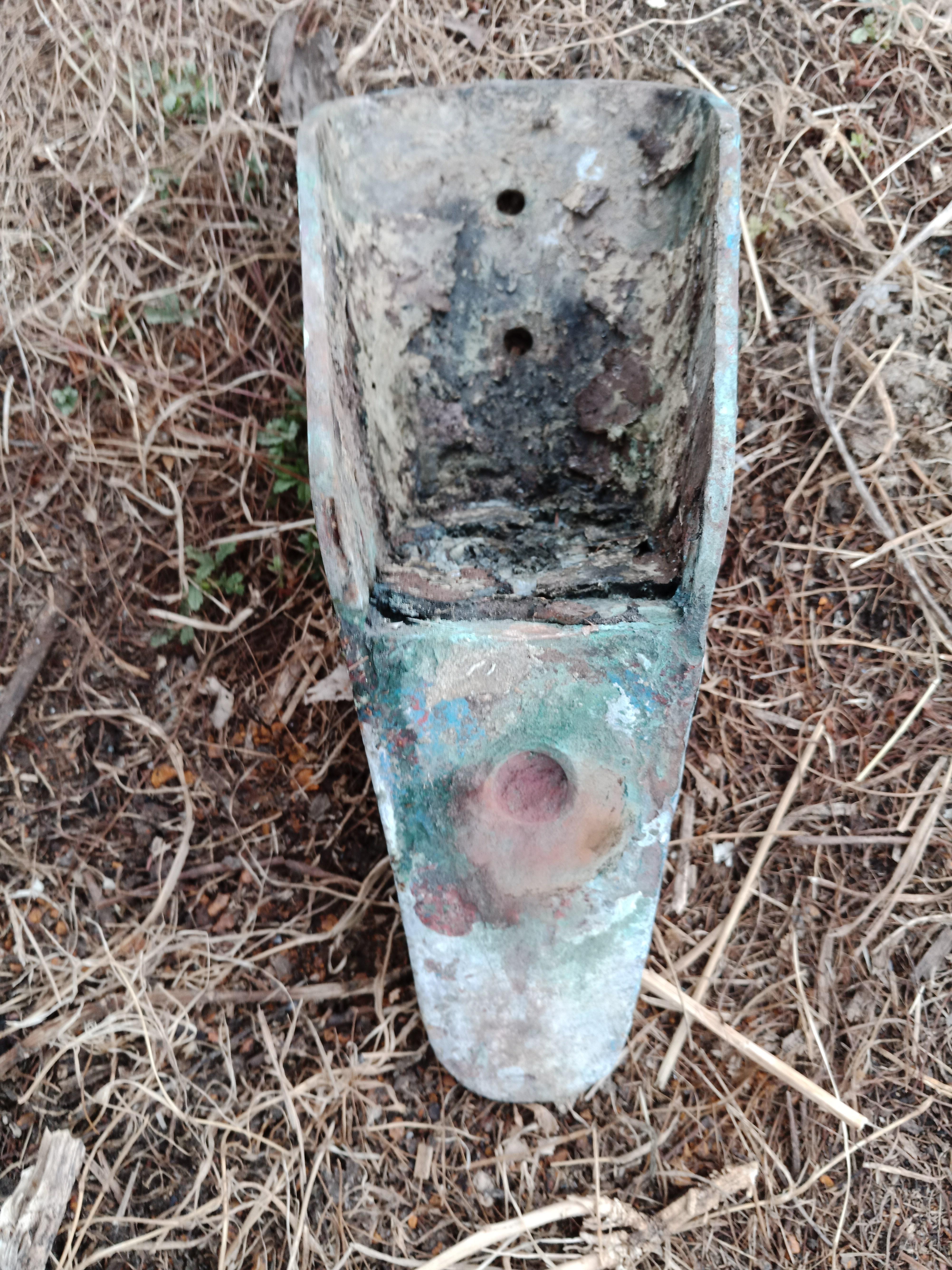
The ‘hole through the rudder’ idea is brilliant thank you! I wondered how I missed it as I had read your page countless times (I just rechecked and you have recently added it – it’s a great idea)
Thanks again
GuyJuly 27, 2022 at 09:18 #27133 Guy HParticipant
Just to update the thread with the outcome – well it was a combination of things.
- the stock was very tight (salt buildup) in the stuffing box area
- one of the rod ends on the steering arm linkage was very tight (not stainless)
- the shoe ‘pin’ had corroded to a pink honeycomb and fallen off
So the rudder was in a very sad state
What didn’t help was where the propshaft had been ‘shoved’ aft to accomodate the rope cutters it also meant you could not remove the prop !!! gotta love the work done by some ‘professionals’ …. so out came the angle grinder (I needed a new propshaft anyway because I am changing the diesel engine)
The collar *still* would not come off after 2 cuts – it mad be made in plain steel
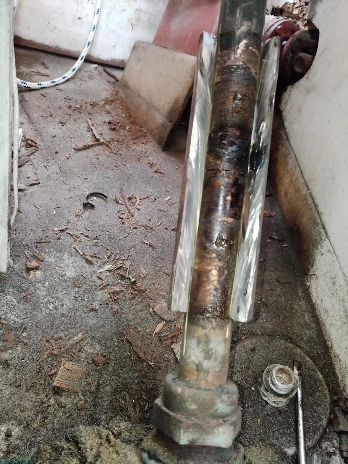
Another cut and managed to lever/hit the final 2 bits off
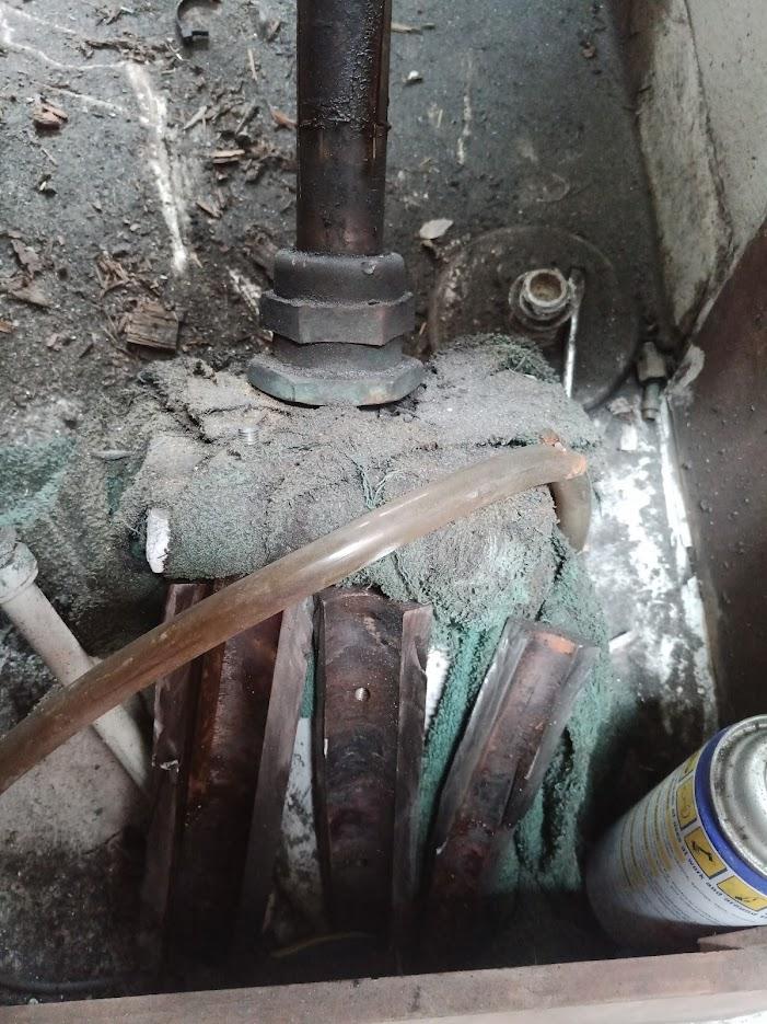
Rudder OFF!!!
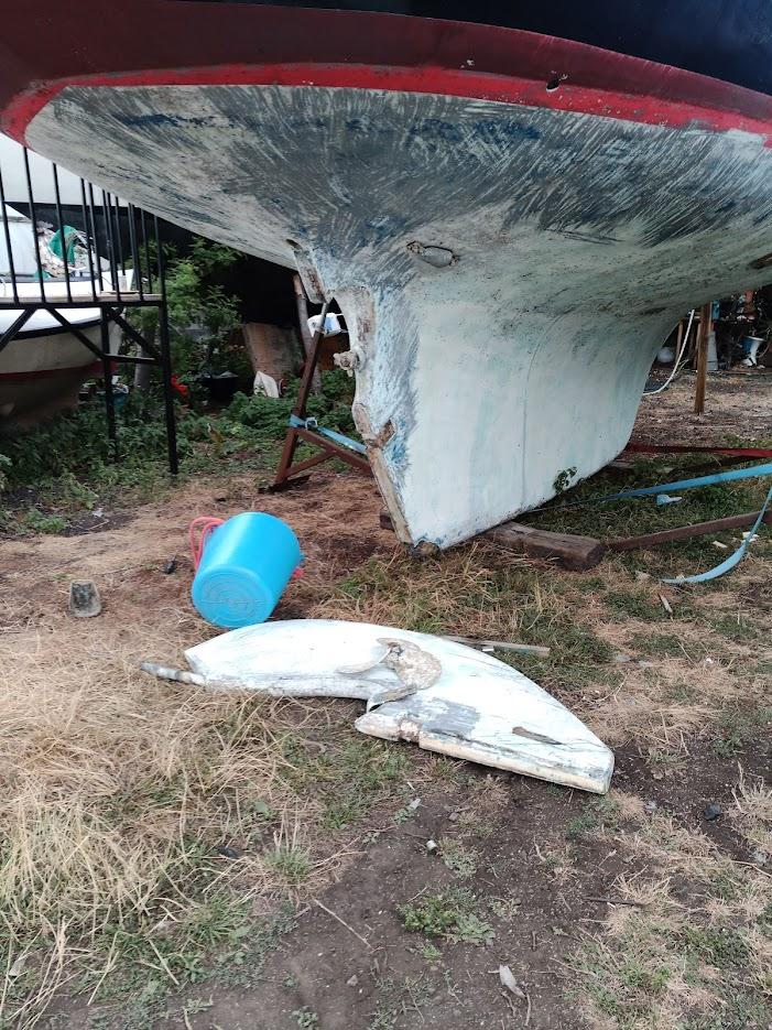
Hmmmmm …..
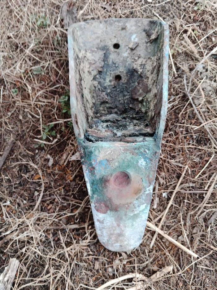 July 18, 2022 at 17:34 #27130
 Guy HParticipant
Hi Marilyn
Yes, I think you are right as there are a couple of areas where the aft end of the keel has worn off the sheathing.

(right click on the image and open in new tab to see full-size)BUT, unfortunately, that not where it’s jammed 🙁
I have been looking at all of your post & photos & couldn’t really see one with the clearance, but I am certainly going to reshape the forward edge of the rudder – the clearance is minimal and the prop aperture is not right.
If I grab hold of the base of the rudder I can move it on the shoe so I don’t think that’s where the jam is either. There is a gap between teh rudder and the shoe so I guess the bearing is in there
I just think that it’s a buildup of salt in the stuffing box or salt and/or marine growth in the ‘tube’ down through the hull.
I will shoot a video which might throw more light either Wed or Thurs (it’s almost 40C here in the UK at the moment & we are just not setup for this heat!!)
Thanks
July 16, 2022 at 11:40 #27119 Guy HParticipant
thanks for your reply – I did buy the rudder drawing and could not see a bearing but wasn’t sure.
I’ve tried steam/hot water, vinegar & various penetrating oils now and they have made a small difference to the movement, but not a lot – I have about 5 degrees of movement now to port, none to stbd and none up/down.
I’m going to remove the sink so I have better access & try to get the coupler off next time with the help of a blowtorch and one of those hydraulic rams (tried without heat & no go)
The coupling is in good condition so it might work.I think I will replace the stuffing box with a Tides Marine bearing/seal here – not sure
I am trying to work out ‘worst case scenario’ of getting hold of the rudder from the outside and just forcing it ….
July 6, 2022 at 12:39 #27110 Guy HParticipant
I thought I would quickly update the thread re my rudder
Interim is now out of the water.
The rudder-saga gets more ‘interesting’.
The rudder had jammed completely solidly since the last post and therefore she ended up on a truck being taken to a very DIY-friendly boatyard slightly closer to home (albeit still an hour each way 🙁 )P.S. to see the full-size images right-click and open in new tab or whatever and you will see the originals
The rudder seems to be jammed in the stuffing box or whatever bearing is below that.
Whilst in the water lots of salt appeared around it – it’s not leaking between the shaft and the stuffing box as that seems *very* dry (and above waterline), so it’s either around the stuffing box or it’s not from water but some other process ?? ….The PO had the rudder re-made in wood. This was then sheathed with a thin layer of glass.
The glass has been rubbed off the rudder on the fwd edge where it’s clearly been rubbing, this has led to water ingress and further damage.
I’m not even sure it was epoxy as the glass has very little adhesion to the wood and there does not seem to have been any resin impregnation as the wood is wet underneath (albeit still solid)So … now I have to try and free off the top stuffing box thing to be able to move the rudder to be able to remove the prop and the U-bracket and then drop the rudder & repair
Is there a bearing under the stuffing box does anyone know?
September 20, 2021 at 21:03 #27059 Guy HParticipant
The 3 and 4 and 5 loop standard handles do not fit the CN38
That’s very useful info – I will make more of an effort to rescue mine then!!
September 13, 2021 at 19:18 #27055 Guy HParticipant
Thanks Roger – you got your head around the photo-posting in the end 🙂
That looks really interesting and I like that it is reversible in the future if required
September 13, 2021 at 17:26 #27054 Guy HParticipant
Try google’ing “Ronstan stanchion cap”.
Thank you – I will get a couple and try them
August 28, 2021 at 17:11 #27022 Guy HParticipant
Hi Roger
Thanks for your reply and that sounds like an interesting solution. (with added benefits)
To insert images, make sure the editor is set to the Visual tab at the top right, click the little landscape button (or shift+Alt+M) then you can upload your image.
In the popup box put 300 in both of the ‘dimension’ boxes and leave constrain proportions checked.
August 27, 2021 at 15:03 #27020 Guy HParticipant
Hi Jeff
… 5 yrs later, but do you still have some of those stanchion tops?I’ve got a broken one on one of my gates so I thought I’d replace all 4 either side of the gates.
Thanks
GuyAugust 20, 2021 at 09:15 #27019 Guy HParticipant
Drop Mads a line on Sail Life YouTube. He’s about to leave Skive (Denmark) to Scotland and was thinking of a 3rd person
August 19, 2021 at 10:19 #27017 Guy HParticipant
As the steering pushes the stock laterally (because the stock does not easily rotate) then the two parts of the rudder stock will angle in opposite directions, so you will end up with a shape like this: < or >. (Imagine the upper line is the upper stock, etc). The top is fixed by the deck bearing, the bottom is fixed by the stuffing box, and the coupler is where the bending happens.
I think you are most likely right there – in one of the other videos you can see fluid moving in & out of the interface between the coupler & the lower stock
The video shows that you have full range of motion. That means the rudder physically can move (eg there is not an obstruction). That really leaves the only causes as being the four contact points for the rudder that Marilyn listed.
Yes, that was about the only thing I could think of eliminating last time I was there. & then thought of using my camera to ‘see’ what was going on
You should get a visual inspection of the rudder. In particular, the shoe at the bottom is made from a bronze part with a pin on it. The shoe is screwed to the bottom of the keel with several self tapping screws. The weight of the rudder should sit on this shoe. If that shoe has failed (dislodged in a grounding, or corroded away to nothing, or the screws came out), then the weight of the rudder will be on a part that is not designed to support that. (The weight is not too bad, as the rudder has some flotation, and is really not that heavy). But whatever is supporting the rudder was not designed to do that, and may be the source of the resistance.
Thank you, I’ve been looking at your blog posts & now really understand all the bits (except what’s inside of the ‘gland bearing’
The ‘box’ that holds the top/deck bearing has delaminated (you can see it clearly moving at the fwd edge where the 4 bolts are) so I think I am going to concentrate on that (& the sagging deck) as I can do those in the water. A haul-out in October is much cheaper for me & I don’t think anything is going to change in those 5 weeks. If the rudder seizes completely then it’s only about 50 yards in sheltered water to the travel lift for me. I will also use those 5 weeks to run penetrating oil inside the coupler – it’s been painted nicely on the outside so i think it was at least refurbished when the rudder was done.
I’m also going to have a good look at the top bearing and probably get a new one made in acetal whilst I fix the box area.
Thanks again
August 18, 2021 at 20:22 #27015 Guy HParticipant
Thank you Marilyn for your reply & the links & thoughts etc
She’s still in the water at the moment.I’m going down tomorrow and will try to isolate it more – last time I was just so fed up with it I wasn’t thinking straight.
Yes, enormous forces are involved as it is bending the bronze shaft before it ‘gives’ and turns a bit. I did mention on Facebok that at least this proves that the rest of teh steering, UJs & mounts etc are in good condition … little wins
The rudder was apparently rebuilt in Iroko & sheathed in glass 5ish years ago, but it is still with the original bronze stock.
The more I look at it I think the main problem is binding in the bush under the packing gland (it’s not the ‘nut’ as that is actually unscrewed in the video.
What is leading me in that direction is the fact that I have removed the nut and there is no lubricating water coming up the bush (that the packing would normally stop leaking)So, I think my plan is to go down there tomorrow, see if I can isolate the issue, take almost all of the tension out of the mizzen lowers and see if anything moves.
In the short-term I am going to book in a haul out in October (as the prices drop by a chunk) and between now & then I am going to repair the deck under the mizzen step.
August 3, 2021 at 11:09 #26999 Guy HParticipant
To change the photo width, edit the reply – use Text mode rather than Visual
look for the link to your photo (I can’t write out what it looks like as the code quoting is broken on here)
After the alt=”” add width=”400″ before the / and then save.
(It should look something like the photo below)P.S. when you see small preview pics on here, you can right click of them and open in a new tab and then see the pic in full resolution & zoom in etc
 July 30, 2021 at 19:46 #26996
 Guy HParticipant
Hi Marilyn
I’d be happy to help with the website
Guy
June 14, 2021 at 20:50 #26975 Guy HParticipant
I can’t quite tell from your photo if your boom is still fitted with the roller reefing. Ken and Jan’s boom is not. Have a look at the first photo on this page: https://svrainshadow.com/?p=983 Just forward of the aluminum boom end where the sail tack is shackled, at the bottom of the black part you can see a hole that a winch bit fits into. That’s the roller furler. I guess this was trendy back in the 70s.
No roller reefing & no slab reefing, I think before it was either up or down.
My setup is different though – external track rather than then the internal one and the old roller drive is that stainless shaft with the pin through it.
All sailmakers I talked to strongly advised against using the boom as a roller furler. So, we had a loose footed main made, which is slab reefed in the normal manner, using lazy jacks.
In the longer term I will get a new main made perhaps even full battened.
But for the moment I want to see if I can make the most of this sail for a year or so.
I am fitting lazy jacks and hopefully sewing up a stack pack as wellThe tack is shackled to the hole on the top of the plate (like your photo after you replaced the cord). Along the luff of our sail are three cringles. The lowest cringle is about 12 inches above the gooseneck. I had the sail maker add that in case I needed to use the downhaul to tighten the luff. I rarely need it. The upper two cringles are for reefing.
That makes sense, yes I understand all that
The downhaul is shown in Ken and Jan’s photo – it’s the vertical rope which they are correctly replacing with a block and tackle. Our has 3:1 purchase and is adequate. The top block is attached to a reefing hook, so I can stick it on any of the cringles. In fact, each cringle has a “dog bone” through it (a short piece of webbing with a ring at each end, on either side of the sail cringle. This makes it easier to attach the reefing hook (and I actually use a snap shackle not a reefing hook).
Yes, that was my thinking as that puts the downhaul load into the luff rather than the through the gooseneck
Regarding the force acting on the split pin, I do not think that the pin is the load bearing surface. If you look, the boom is resting upon the slider that fits into the mast. The clevis pin the is the hinge that allows horizontal movement, and is not load bearing in a vertical direction, only horizontal. So the split pin should not carry any load.
I thought the ‘ring’ to which the down haul was attached was an extension of the pin. I don’t have a fitting like that on my slider. But I’d prefer a cringle in the luff and use that.
While we are talking about it, pay close attention to the hex head bolt just aft of the slider, that provides vertical freedom of motion. On our crossing from Seattle to Hilo, our crew discovered that the nut had worked its way off and the bolt was simply held in by luck and a bit of friction, and had already started working its way out. Scary! Crew got extra grog that night.
I’ve got a completely different end on mine. No bolt, just a captive pin.
The rectangular hole on the starboard side is for the outhaul, which is internal to the boom. Check the link above for a full description of the outhaul.
My outhaul is wrong somehow – I have been looking at your article and can’t quite get my head round it. I’ve got an endoscope camera for my phone so I am going to have a poke around in there to see if I can see what might be missing.
Thanks for all your help 🙂
June 14, 2021 at 20:27 #26973 Guy HParticipant
I thought I read somewhere in all the paperwork that they are bolted into captive ‘nuts’ that are glassed in. Obviously helps with stopping water ingress but if they break or snap in there it might not be so great!
I need to do the same as the rear end of the stbd hand rail has come away!
-
AuthorPosts