
@van
Forum Replies Created
-
AuthorPosts
-
 VanParticipant
Chocolate boxes!? Wonderful name.
I ran into this issue too. I decided to use simple connectors, like the ones used to connect wiring on a trailer to a truck. Not very elegant, but cheap and easy to wrap with tape to waterproof. I suspend them from the cabin sole to keep them out of the bilge.
I also use a DB25 for the connection for our old DataMarine anemometer. It’s shielded, and has enough wires. I “waterproof” it with many layers of electrical tape.
I also squirt in some dielectric goop into the connectors’ holes – it’s called “Stuf” and is often used by Hams. I use it for PL259 UHF connectors for the SSB and VHF radios.
Van
VanParticipantHey Trevor,
We just did this with Rainshadow – re-stepped the mast last Thursday. Pulling it out was straightforward. Obviously disconnect all wires – there there was a bonding wire that I almost missed as it was out of sight.
We have a roller furler – Harken Mk IV. It was necessary to disconnect this from the stem fitting during the haul out as the travel lift was not quite long enough to deal with it. At the dock, I simply released it at the stem fitting (also easing the backstay), and while it was still attached at the head, walked it down the side along the outside of the lifelines to about the level of the forward stay, where I tied it off to the lifelines. I used a halyard as a temporary stay, dropping that only when the travel lift was carrying Rainshadow. The mast is pretty strong and the halyard probably is not needed, but it seemed prudent. You will also have to do this to unstep the mast.
When it came time to unstep the mast, as the crane operator lifted the mast, one task for me was to keep the furling drum from snagging on the lifelines. Then, as the mast came out, I strapped the furler, along with the shrouds to the mast as high as I could reach. The crane operator then lifted it over the side and lowered it until the foot was about a meter from the ground. At that point, I went down to ground level and as the operator lowered the mast, I walked the foot forward to rest it on a saw horse. The other end of the mast slowly was lowered onto another saw horse. It was pretty straightforward. Just make sure the spreaders don’t catch on anything. The crane operator here didn’t always have a good view. We used just two saw horses and that was plenty. The mast sagged a little but seemed fine. I tied everything to the mast in three or four places.
Also, the crane can interfere with things at the masthead, such as a windex or anemometer. In our case, it was fine and we didn’t have to do anything special – just watch for that. Also, another thing that can get dinged is the mid-mast lights (steaming or deck light). Again, just watch and if there is a problem the crane operator will wait until you can swing the mast to avoid a problem, or he’ll have to adjust the crane to avoid problems.
The mast has a very nice rubber “partner” (if that’s the right word) which jams in between the mast and the deck to hold it secure. This was a tight fit and I had to go below and whack it many times to pop it out. You will need a mallet and some kind of shaft/rod/stick to be able to get at it. Just pulling the mast up was not enough, you have to pop the rubber thing out to be able to get the wires past the deck. Be careful, I missed and whacked myself in the nose…. embarrassing and lots of blood! Haha!
One more thing, the mast can roll on the saw horses, so keep a couple of wedges handy to jam on each side to stop that.
Restepping the mast was similar. Watch for the crane harming something. Once it is in position to lower, move the furler outside the lifelines again. Make sure the mast boot and partner are ready. I liberally soaped up the partner to make it slide easier and this seemed to help.
The step itself is a long slot, with four wood blocks on either side of the mast. I took out the forward two blocks as the mast was lowered, and then wiggled the mast until I could get them back in. I did not have to whack them.
It really helps to have someone relay commands from you, in the head guiding the mast, to the crane operator. But you have to shout pretty loud to be heard via the fwd hatch. In all it took about 20 minutes to restep the mast, which included reattaching all the shrouds at the chainplates.
Van
VanParticipantHi Gerhard,
Our sails were made by North Sails, and the battens use a slider which is indeed too large for the gate above the goose neck. So, to install/remove them, I have to drop the boom down until it reaches the large gap in the track near the deck. It’s a hassle, but only twice a year.
Having said that, I am not too happy with the sliders because they require the mast track to be clean and lubricated (MacLube or silicone spray for instance). Otherwise, they can bind when raising/lowering the mainsail. An option with bearings or wheels would be nice. Another option is the STRONG sail track system. A local sail maker (Port Townsend Sails, who we hired to upgrade the North Sails we got to make them “cruise worthy”) recommended this though we chose not to get it (in hindsight, I wish we had).
I also wish we had gotten full length battens – two of the four we got are only partial. Live and learn!
Regarding anyone using the roller boom, I asked many sail makers about that, and they were unanimous in saying it was a bad idea. Something about having to have the topping lift hold the angle of the boom exactly right or the sail would not wind properly. And of course now the trend is for mains to be loose footed. Perhaps in another 40 years, roller booms will be back in fashion…..
Van
VanParticipantWe have two panels installed just forward of the pushpit against the lifelines. The previous owner installed panels there back in the mid 80s (he was ahead of his time) and they were nominally rated at 45W each but were now putting out about 15 each. I upgraded them to 85W panels from BP Solar. Model BP 485J. The issue was finding something small enough to fit between the pushpit and the stanchion, and not too wide (tall) that it would protrude too far above the lifeline.
Based on the PO’s original design, I built a frame out of 90 degree angle aluminum, with a s/s piano hinge at the top that was riveted to the frame of the panel. They can lie vertically (ie against the lifelines), or be raised up with a stick so they are parallel to the ground. Very often, part of one is in the shade and does not produce useful power.
The wires run down the aft scupper and into the engine room – the PO did this and I just reused them. He somehow managed to get the wires down below the deck level, and then punched through the sides to get into the interior of the boat – and gooped it up with some kind of polysulphide goop to seal it. I would not have done this – but fact is it does not leak (so far!).
In hindsight, I should have wired some kind of connector inline, so that the panels could be taken off and stowed below. They surely create a lot of windage, and a big wave would smash them to bits or worse. Would be nice to be able to remove them if a serious storm were due.
I use a Blue Sky Solar Boost 2000e MPPT controller. Only complaint is that it has bad RFI – if it’s producing power, I can’t use the SSB, eg for the evening net around here at 6pm local on 3.5MHz.
In sun here at Lats 48 – 52, we get 10 – 12 amps at >13.2V for most of the day, ie over 100 amp hours.
With this power input, we can run the boat indefinitely – if the sun shines. For instance, I spent three weeks in June on the boat running the fridge and computers and lights, etc, with no shore power and no engine/alternator power. But it was sunny!
More power would be good so I do toy with the idea of two panels in the area you are considering. Will be interesting to hear what you learn!
Van, in cloudy Port Townsend rebuilding the rudder….
VanParticipantIf you think it might be worth trying to clean the heat exchange to deal with the overheating, you may want to look at our experience with Rainshadow’s 4-108 heat exchange. We posted a description of the project here: http://svrainshadow.com/?p=288
Also, you might want to verify that the temp gauge is accurate, and the overheating is not just an uncalibrated gauge. I have one of these nifty handheld optical pyrometers you can get for just a few tens of dollars. We use it to measure various points on the engine – for reference and possible use in troubleshooting. For instance, I know the heat exchange body should be about 170F on the raw water/fresh water side, but 130 on the raw water/oil side; and the raw water outlet is about 100F.
VanParticipantHi John, I redid the panel as part of a major overhaul of the wiring on Rainshadow. This was definitely a worthwhile, though time consuming project. Most importantly, it gave me the chance to implement a number of safety features.
Thinking just about the panel, replacing it does give you the chance to make sure the fuses/breakers are sized correctly for the wires and devices they support. The original wiring (rather, the wiring we inherited from the previous owner) was not fused correctly, some very small wires having large breakers, and more than one wire was not fused at all.
I gave a lot of thought to the panel, and considered the same panel Jeff used, but in the end I opted to rely on fuses to protect wires at a very granular level that I could not get with breakers. In other words, essentially every wire on the boat now has its own dedicated appropriately sized fuse, and the wires are grouped together into “circuits” protected by one of eight 15A breakers. When I did this, it turned out that I only needed eight circuits: 1) Cabin lighting and such, 2) the Refrigerator, 3) the Radar, 4) the Webasto diesel heater, 5) Running lights, 6) Sailing instruments (like knotmeter), 7) the Helm and 8) the Nav station (chart light, computer, etc).
The fridge, radar and heater are on dedicated circuits.
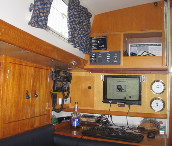
I placed the panel in an instrument box I made above the nav station (there was originally a smaller one). In the recessed location where the old panel went, I placed two fuse boxes, each holding twelve fuses. One fuse box serves circuit 1 (Main) and one serves 5 (running lights). There are also fuse boxes under the nav station for 8), and one in the instrument box above to serve 6). Finally, the helm 7) has a fused switch box (waterproof) under the wheel. So, apart from the three dedicated circuits, every circuit has an associated fuse box, and plenty of spare capacity.
I replaced the switches for the nav lights with new ones, but they remain in the recessed location where the old breaker panel was.
The bilge pumps are on a dedicated circuit, directly connected to the house batteries (fused of course).
Finally, there are several weird items, like the input to the batteries for the solar panels, and the engine hour meter, etc that should not be on a circuit breaker that someone can turn off, but nevertheless need fuses. I added a dedicated fuse box in a container in the stb cockpit locker on the bulkhead shared with the nav station.
I thought about writing this up in more detail in our web site svrainshadow.com, but have not got around to it – however this gives the flavor of what I did, and the main motivation.
Everything has worked fine for the last year.
Almost all the components are Blue Sea Systems.
Good luck!
Van
 VanParticipant
Hi Charles,
yes, the halyard restrainer is mandatory. Because of the geometry at the mast head, without the restrainer the angle of the halyard to the swivel at the top of the furler is too small to prevent wrapping. The restrainer was easy to install, it’s held on with six fasteners (I used machine screws which required tapping holes, but a local rigger told me I should have just used monel rivets which are faster and simpler).
We used the long link plates to get the sail foot over the pulpit rails, and get the drum out of the way of the ground tackle. We almost always anchor (avoiding marinas) and that’s an area where you don’t want to be cramped for space. I sometimes wish I’d had slightly shorter link plates to get a little more sail area, but really, it’s not a big deal.
Re Marilyn’s point about sail plans, the problem with our 130% genoa is that in order to be useful as a heavy air sail when partially furled, it has to be strong and therefore heavy. This makes it a poor light air sail.
OTOH, when reefed to say 80%, it has poor shape. So, it’s not really optimal in either set of conditions. Contrast that with a hanked on light air sail on a solent stay, easy to set and douse and very effective in light airs; pair that with a strong working jib on the furler and you get great light air performance and great heavy air performance.
Of course, eventually, even the furled sail will be over powered, and then you’ll be hanking on a storm jib onto the solent stay.
Well, that’s the theory and someday I plan to change our plan to that.
Van
VanParticipantThanks – these are good leads. We are probably stuck with using off the shelf parts from here, meaning a bit of a kludge but it will work. We don’t have time to spare – Thanksgiving is this week and nothing happens fast, and then Tuesday next week we are gone until May. Our mechanic can get it completed Monday if we go for the local kludge. In effect they are making an adapter – from the UNF on the lift pump to a copper tube to a JIC fitting they can connect the hose to. All annoyingly complicated, but hopefully it will work. At least I now know where to go to get the right parts….
Thanks,
VanVanParticipantHi Trevor, have a look at the photo here:
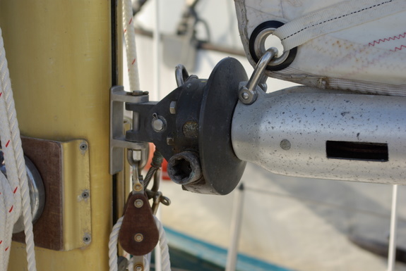
(be patient for this to load, web server is sloooowww).Is this what you mean? I would assume if you are having some parts remade, you will need to have some dimensions. I just took off the sails yesterday so the boom is free and clear to take photos with a tape measure in them. How much did you lose? I never took off the roller mechanism. I reckon it just gets in the way – maybe this is a chance to make a replacement that has the fittings/attachment points you want!
Let me know what dimensions you need and I can easily measure them – obviously the distance from the pin in the gooseneck to the start of the aluminum boom is an important one. I’ll be down on the boat a lot over the next few days as we are doing some engine work and I have to winterize the systems. You can email me at v a n e d e n (at) hotmail.com – no spaces of course.
Cheers,
Van
VanParticipantRevisiting this topic. We recently met with Port Townsend Rigging (very well respected rigger here in the Pacific Northwest) and had an interesting conversation about this (I did not prompt him with any of the solutions suggested above). Firstly, the rigger suggested adding a U bolt to the bollard was likely to be a good connection (per Roger). He suggested the center bolts or if it’s possible to get a fair lead, the forward bolts – we are looking at using the solent stay for hanking on a drifter and for that you want it as far forward as possible (but not too close to the forestay).
He also thought that putting a double folding eye forward of the bollard and underneath attaching that to the fiberglass plate under the stem fitting (which you can see in the photo above) would also work (per Ronar). Finally, it took him a while to grok my idea of using pennants from the bollard and stem fitting, but he liked that idea too! It uses two existing strong points, and requires no mods to the deck.
What was most interesting was his reaction when we talked about the construction of the deck – first class, super strong. I think that’s why he was comfortable with all three solutions.
For the mast fitting, he’s recommended a “staysail bracket” from LeFiell (lefiellmarine.com), riveted to the mast just under the cap shroud tangs. I guess they are about $90.
We do have one complication. The previous owner installed a windlass just forward of the bollard, and to do so, he cut one athwartships stringer and a couple of longitudinal stringers. This has weakened the deck, and you can see it move when loads are placed on it (by the windlass or by a person stepping on it). This is not good, and the rigger has recommended chopping out the cut stringers, grinding the surface and installing a 3/8″ tempered aluminum plate under that area (including under the windlass). I think we’ll do that, perhaps next year.
Cheers,
Van
VanParticipantOne finding in the earlier thread was that an 18 inch diameter prop is really close to the deadwood and causes a lot of vibration and noise. We had a similar problem on Rainshadow, but in this case it was a 16″ prop too far forward. For an exhaustive (exhausting) analysis of the prop question, see our blog at http://svrainshadow.com/?p=719. We are quite happy with the fixed three blade prop we got from Axiom. It’s 15.25″ diameter. However, because of the smaller blade area it does suffer from cavitation above 2500 RPM. In hindsight, I might have tried a 16″ diameter prop to get a bit more thrust and reduced cavitation, at the expense of perhaps a little more noise from the shock waves on the deadwood.
Good luck,
VanIf you are so inclined, the book Propellor Handbook by David Gerr is very good.
VanParticipantHi zigzag,
I’m not sure what the AV control box is. Is that the circuit breaker panel?
We redid the wiring on Rainshadow and can tell you it’s of generally of high standard, although some modification by the previous owner were not so great, although safe enough. The only chafe I found was a wire put in by the previous owner (ie not C&N). This was a 16 gauge wire carrying 12V that had its conductor exposed, but fortunately, not close to any grounded/earthed objects. Most of the wire is not tinned, but the connections were clean, and only a few wires showed much evidence of corrosion.
The main problems you will likely find are:
1. The circuit breaker panel – one of our breakers became unreliable after 35 years so we replaced the panel with a modern one. Replacing the panel was quite easy and gave us the chance to identify and label all the wires behind it. There were many that were not connected to anything any more.
2. Prev owner added a high output alternator (a common upgrade) – exceeding the nominal capacity of the wires carrying the current to the helm where the ammeter was. We’ve replaced that with a remote shunt and a new meter so the current does not have to travel an extra 15 feet to the helm and back.
Using two battery banks is standard practice. We use a single starter battery for the starter circuit and two golf cart batteries for the house. In your Nic 42, you probably have more space. Perhaps the previous owner wanted the extra capacity. The original two battery switches permitted either battery to feed the house circuit and/or the starter circuit. We replaced those too.
Good luck!
Van
BTW, s/v Gosling is another Nic 42. Jean-Guy occasionally posts on this forum – you should read his bio in the Members Directory (see the link at the top of this page – you need a password which if you don’t have Marilyn can send you). And look at his blog at http://svgosling.blogspot.com.
VanParticipantYou can calibrate the steering compass by simply rotating the compass unit. It is held down by a couple of screws/bolts in slots so you can rotate it to adjust for errors like that. Not terribly accurate, but good enough.
VanParticipantHi Trevor,
If you let it, would the Neco steer you in a giant circle? Makes me wonder what kind of control circuit logic it uses.
The instruction manual section 4.1 describes “Lining up on Installation” – this is probably what you mean does not make sense. It sounds a lot like what you are suggesting, but they don’t disconnect at the final gearbox, instead they disconnect the chain from the drive unit.
Note that they disconnect the compass cable from the system during this set up. This will make the drive unit run to its neutral position (so the instructions seem to indicate). Then they set the rudder amidships, and at that point reconnect the drive unit to the chain (step 6).
If you do align the Neco with the steering by aligning it with the compass heading, it would seem you are presuming that your compass heading was correctly calibrated. Also, when you switch on the autohelm, it will either not move (it’s happy) or it will never settle until you move the Neco dial to exactly coincide with the steering compass. Of course, you also need to make sure the rudder is held amidships until you reconnect the gearbox.
Good luck!
Van
VanParticipantHi Roy, thanks for the advice. We have stainless turnbuckles now, and we will replace them with Bronze!
Spoke to Hayn, who make Hi Mod mechanical terminals, and they said they don’t make fittings for 9/32″ wire with 7/16″ pins, because the pins are undersized for the load the wire can take. I think this might be a case of the wires are a bit over sized for the job, but I’m happy to let C&N designers opt for safety…. So, we’ll ream out the tangs next time we drop the mast, probably next summer. In the mean time, we’ll use 7/16″ pins in the holes. Not good, but I think OK for a year of coastal sailing.
The cost for all the parts is coming to about $1000 for the two shrouds and the backstay, using 316 wire, and including one insulator for the stbd shroud. The only components we are reusing are the two StaLok studs on the shrouds. Of course, we are doing the work ourselves, and swapping the wires without unstepping the mast. Makes me really appreciate the mast steps that make it easy to get up and down.
Van
VanParticipantThe specific asymmetrical sail we are going to get is made by Yager Sails, over here in Easter Washington. Here are some photos that show the sail pointing: http://yagersails.com/spinnaker.html. Yager sails is a small loft, but he’s come up with a rather nice design. The sail doesn’t have a luff rope like eg the Doyle UPS, and yet it can still point well. Won’t be until April or May that we can test it as we are away.
VanParticipantHi Pat,
We got a new set of sails just over a year ago. All the advice we got from the sail makers we talked to was unanimous in thinking the boom roller furling was a bad idea. Too finicky, I guess.
Suggest you talk to a few sail makers and have them measure your boat. We went with North Sails and it was a disaster so I can’t recommend them at all. I hear that they have a set of standard patterns and they pick the one that closest matches your measurements. If this is true, they obviously picked the wrong one for us. The luff is several inches too long, requiring that we drop the boom that much from its nominal position. So it now is very close to the coach roof. They also gave it far too much roach, so that the battens would hang up on the backstay. They recut the roach but did nothing about the luff. They also screwed up the genoa. All in all a very bad experience – anyone can make a mistake, but the way they handled it was bad. Go with someone who cares about their reputation!
We also got advice about reef points: we went with two points, with the second reef point being quite deep. If we get into conditions where a third reef point might be wanted, we’ll drop it all together and fly jib and jigger (mizzen).
We went with two full and two partial battens, and that seems to work well for us. People argue that the wear is worse because of the battens, especially chafe where the battens hit the shrouds, but we will just keep a watch on that.
The main was made of Dacron (NorDac), standard cut. Also, all the sail makers advised having it cut loose footed, the idea being you can get a better shape that way. However, that does mean your outhaul has to be working well, and IMHO the original outhaul is a bit weak. Search on the forums here for another thread about the outhaul, and you can also see what we did on Rainshadow if you go to http://www.svrainshadow.com. I doubled the purchase from 3 to 6:1 by adding another block inside the boom. Have not tested this yet (she is mothballed for the winter).
We are now talking with another sail maker about a light air asymmetrical sail that can point to 40 degrees.
Van
VanParticipantHi Kenneth,
Rainshadow – hull 126 – has removable slats fwd of the berths. There is a non-removable wood “bulkhead” that is level with the tops of the cushions, so it about 4 inches above the level of the v-berth plywood. It extends down into the apex of the V.
I suspect the main structural aspect of this bulkhead is the area below this level, where it is solidly glassed in.
I’ll try to attach a photo.

VanVanParticipantHi Adrian,
We looked at this issue a while ago and opted for a fixed prop, from Axiom. It has good thrust, and is sized correctly for Rainshadow, allowing us to get to the recommended 3200 RPM at top speed of 7.5 kts. We do have some noise at higher RPM, but we can comfortably cruise at 5 kts (2000 RPM) – 6.5 kts (2500 RPM).
Where it really shines is in reverse. No prop walk to speak of, and we can reverse Rainshadow confidently and easily, with plenty of power. That was what attracted us to this prop. The previous screw prop was horrible.
Also, Axiom support was super – the first prop sent was incorrect so true to their word, they sent us a new one at their own expense. Really a pleasure to work with them in spite of the first prop not being quite right (the issue was the aperture was smaller than they realized so the blades came too close to the deadwood).
You can see more on our blog at http://svrainshadow.com/?p=827
We felt that the benefit of the extra 1/2 knot was not enough for us to justify the cost. In general, if you have enough wind, there is more than enough power in the sails to drive the boat faster and overcome the drag from the prop. Or put another way, the 1/2 knot effect probably is only important in light air. Our philosophy with that is to get a big light air sail (more on that later).
Finally, we also talked with Darglow Eng about their Featherstream prop, which looks quite interesting and not as expensive (at that time) as the MaxProp, Autostream, etc. See http://www.darglow.co.uk/html/products/feather.htm
If we had not gone with Axiom, we probably would have tried the Featherstream.Let us know what you decide and how it goes!
Van
VanParticipantHi Peter,
My first attempt using the plastic railing is not satisfactory because it’s a bit flimsy and too wide to easily get past the shaft. So, when I’m putting it into place, the floats and pumps tend to shift unless I’m careful.
One additional point, if you make the length just right, then the board can hold down a strum box firmly to the bottom of the bilge.
When it warms up here, I’m switching it to a pressure treated wood 2″x4″.
Van
VanParticipantFinally finished the new outhaul – I did add another block to give a compound 6 to 1 purchase. It seems to work well, but I have not tried it yet with a sail. And I replaced the “string” with a Dyneema line that has a 1200 pound strength 🙂
I’m also going to take a lot of care in screwing the boom back together. I think I’m going to lather the end fittings with lanocote before I stick them back in the boom, and goop up all the stainless fasteners with TefGel. I hope that means it will always be easy to get the boom apart. We’ll see!
Van
VanParticipantI’m considering attaching a U shaped tang (if that’s the right term) to the mast at the bolt where the main cap shroud tangs are attached. My presumption is that because this point is strong enough to take the sideways load of the shrouds, it should be strong enough to take the forward load of the forestay. I’ll simply need to get a longer bolt to make room for the thickness of the tang. I’ll connect the forestay to the bottom of the “U”. I’ve not worked out the dimensions yet, but it needs to be long enough to provide a fair lead for the stay, and strong enough to handle the forces. I’m assuming the working tension will be similar to the tension on the backstay (1,200 lbs) which is a bit more than the typical tension on a halyard (about 1000 lbs). The main worry I have with this idea is that the U will lay against the halyards when not in use, or get in the way somehow.
The attachment point at the deck is a bit tricky because of the new roller furler drum, and a windlass just forward of the bollard. That part of the deck is strong, however there is not a lot of room there. Also, I hate the idea of yet another hole in the deck, and the effort of reinforcing it, etc. So, my current plan is to use two pendants – one attached to the hole in the stem fitting that is meant for the boom foreguy (i.e. the aftmost hole) and the other attached to the bollard possibly by the addition of a hole and shackle in the bollard). Then, the two pendants and the deck form a triangle at the top of which is attached the removable forestay, and by adjusting the length of the two pendants, I can move the lower end of the forestay forward or aft. This also has the advantage of sharing the load between two known strong points that are already plenty strong enough. (In fact, probably 90% of the load will be on the stem fitting).
My rigger is recommending Dynex DUX for the stay as it does not creep.
Lastly, I have a storm jib in excellent condition that was made for hanking onto the forestay. I’m hoping it will fit well enough. That’s a motivation for keeping the removable forestay as close to the actual forestay as possible.
Van
VanParticipantHi Pat,
I just rebuilt mine as the part with hinges had failed due to water getting in via the screws (not bedded or sealed properly), and the freeze-thaw cycle cracking it apart. But the main part of it is still fine. I ground off the gelcoat and dug out the wood inside, and replaced it all with epoxy and fiberglass. I have not yet replaced the foam/rubber seals.
It would seem to be quite a project to make a new one!
VanVanParticipantHi Roy, I owe you a beer (or three).
Like I said before, you inspired me to have a go, and yesterday, I finally finished the repair, and everything works now! Really appreciate your help. I’ll write up some notes on the process and put that on our svrainshadow.com blog. The hardest part (besides overcoming my own stupidity) was finding a source for the O-rings. A diesel injection pump repair place mailed some to me, but the one for the stop control broke as I was installing it (I think it was defective). We had to drive to Pt Townsend (over an hour) to get a replacement – none of the local diesel shops, or auto parts shops had them in the right size. But, it all worked out in the end, so we’re happy.
BTW, you are exactly correct about just removing the outer casting retaining bolt and being able to pull out the throttle spindle and replace the o-ring. But we figured we should replace the stop control spindle o-ring while we were at it.
Van
VanParticipantHi Roy,
Thanks for this advice – you inspired me to try it. I spent much of today cleaning the engine, draining the coolant, and removing the manifold. Fortunately, the previous owner stocked up on spare gaskets so we are set for replacing those.
Now, I have good access to the pump – except there are two fuel lines that pass over it. Can you tell me about how much I’ll have to pull the spindle unit up? I think there is only about 3/4″ of space. Should I just disconnect and move the fuel lines?
Thanks!
Van
-
AuthorPosts