Welcome Back › Forums › Propulsion › Engine › Exhaust leak 2
- This topic has 14 replies, 5 voices, and was last updated 6 years, 9 months ago by
 Ronar M.
-
AuthorPosts
-
November 19, 2012 at 16:57 #6281
 Ronar MParticipant
Hi All
Have made a start on my exhaust leak problem and want to put some pictures on the site so had to start a ‘new’ topic.
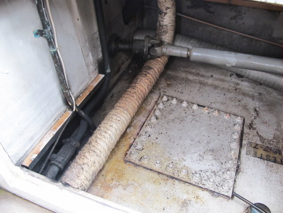
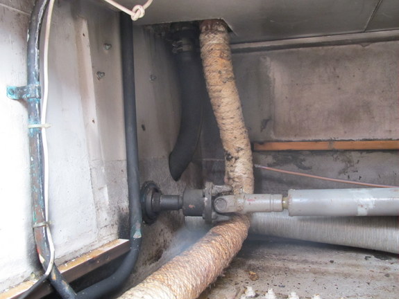
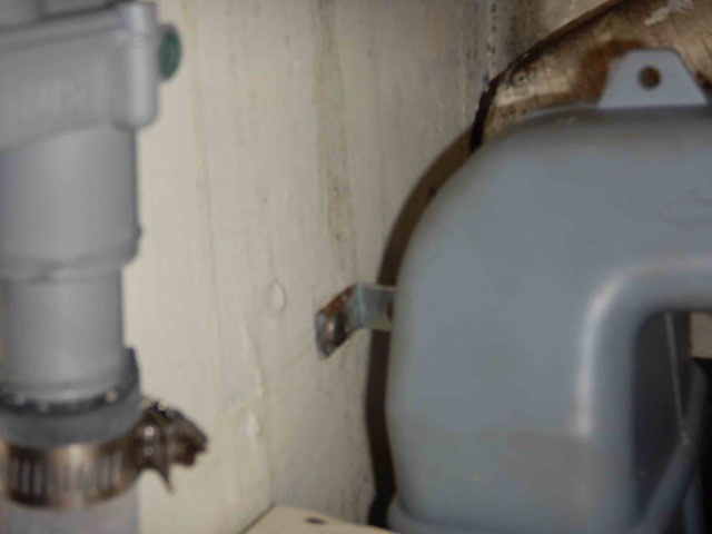
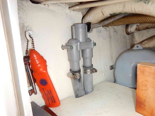
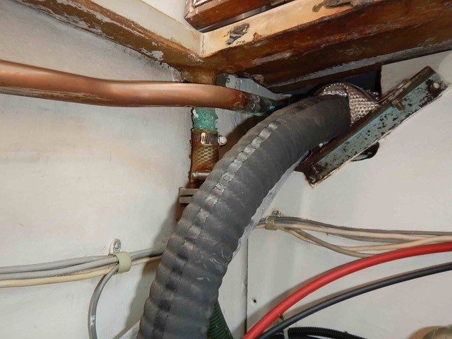
As I said before, the leak seems to be where the pipe disappears under the port side lower cockpit locker. Yesterday I took the back panels and floor out of this locker – just a matter of taking out a few screws (some of them in rather diffcult-to-reach positions but, compared to some jobs on the boat, relatively easy). The back panels came out easily once all the screws were out; the locker floor needed a bit of manouevring before it came out. Anyway the exhaust is exposed in all its glory (wrapped in insulation)as you can see in the pictures. Next time I get down to the boat I reckon I will have to disconnect the steering shaft at the UJ you can see in the picture and then hope to be able to withdraw the pipe into the engine bay.
Will keep you posted
Cheers, Trevor
 November 21, 2012 at 11:05 #12621
 Chihili QParticipant
Interesting; I wondered what you were on about referring to wing tanks; my fuel tank is under the companionway steps, my cockpit lockers are gaping caverns without partitions; a bit wet for sails really but I hope to remedy that in time. This space in Ronar’s locker might be begging a heat exchanger if you haven’t installed one already; I haven’t but it’s on my wishlist. What an amazing variety of modifications we see posted!
BW, Adrian.
November 25, 2012 at 13:47 #12681Ronar MParticipantHi Adrian,
I have already fitted a heat exchanger (calorifier) in the engine bay. It fits very neatly on the port side of the engine. Cheers, Trevor
April 1, 2013 at 19:41 #13341Ronar MParticipantHi All
Just want to report how I solved my exhaust leak. The pictures above showed the old pipe and its lagging. I decided it would be easier to replace the whole tube rather than part of it as a newer stainless steel section in the engine bay was a different diameter to the lagged portion in the photos. So I detached the flange from the engine and had a 38mm s/s tube about 3″ long welded to that. I took off the flange at the other end where the steel pipe joins the box where the water is injected. I had another s/s 38mm tube welded to that and connected the two with over 2 metres of ‘polylock’ s/s flexible exhaust pipe wrapped in exhaust lagging. I connected the polylock tube to the flange tubes with special s/s exhaust clamps, two at each end, and exhaust sealant. I thought the central section of this flexible pipe needed supporting so I fixed some angle aluminium under it (held in place off the bolts on the diesel wing tank) and clamped the pipe to this using a standard automobile exhaust clamp. Bingo. It works like a dream.
Trevor
Ps. when I took the old pipe off I found that its internal diameter was less than the size of my little finger – blocked with hardened soot. How the engine worked with this I will never know.
Pps I chose 38mm tubing as this is a standard size and nearest to the original exhaust diameter.January 9, 2017 at 11:04 #26004Ronar MParticipantHi All
The account above is not the end of the story. On my way from Plymouth to the Isle of Wight last summer for the Round the Island Race we were motoring with no wind. Gradually the smell of exhaust increased to unacceptable levels so we found an anchorage and investigated. The flexible stainless polylock tube had broken completely just where it joined the water injector. I was able to strip back the insulation and remove the remains of the pipe. Luckily there was enough spare in the main body of the pipe to pull it up and fix if back on the water injector as a temporary repair. One of the crew had had something to do with trucks and he said they regularly use polylock tubing and it regularly fails.
Polylock tubing is not cheap so I have plans to get a solid stainless pipe made up and only use the polylock at the two ends where it joins the manifold and the water injector. The problem is how to support the exhaust pipe with flexible fixings to allow for vibration. Ronar has wing tanks so, as you can see in the pictures above, the exhaust runs over the spare diesel tank. I cannot drill any fixings into the tank so I’m toying with the idea of fibre glassing some wooden bearers to the top of the tank and fixing the exhaust pipe to then via flexible fixings. I’m hoping more flexibility will make the exhaust pipe last longer. Watch this space. Cheers, TrevorJanuary 20, 2017 at 00:51 #26008 VanParticipant
Interesting to read this Trevor, thanks for posting. This is a part of the engine we have not really had to deal with. The previous owner had to have the mixer removed and repaired to fix a hole. But the tube is original I expect.
January 23, 2017 at 00:21 #26009racepassage
ParticipantHi Folks,About 2 years ago pulled out entire engine compartment exhaust system and installed a Vetus system. that is, from the engine manifold exhaust is piped to a Vetus simple mixer (water lock) then up to the Vetus gooseneck attaching to the existing exhaust pipe through to the transom. A simple Vetus air vent is also included which exits through the hull at cove stripe level (port side) just behind the side gate. It means that when at the wheel I can easily see the thin stream of S. W. coolant flowing out. If it stops then I know there is no S.Water intake!!!
The installation was easy, all Vetus parts and hose fit perfectly, so no worries.
Will attempt to enter pictures.January 23, 2017 at 17:38 #26016 ModeratorKeymaster
Here are the pictures that Roger (RacePassage) sent to show his Vetus system. Very cool! (no pun intended).
Roger, any chance you could share part numbers for your chosen system. I checked the Vetus catalog and there are quite a few sizes available for the items seen in the pictures.
Thanks for sharing this info.
Marilyn the moderator.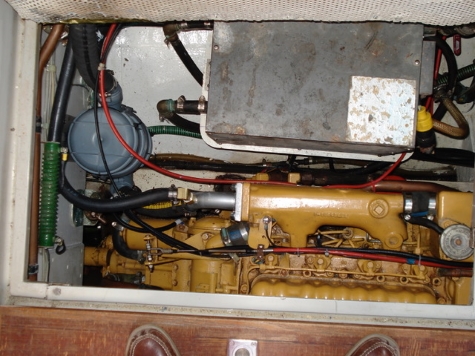


 January 29, 2017 at 23:09 #26022Participant
For the interest of those who are contemplating renewing their exhaust system here are the Vetus part numbers including hose lengths etc.
Qty Item No Description Per Unit1 91-717 Waterlock 1 5/8”, Plastic, NLP40 EA
1 91-739 Gooseneck 1 5/8”, Plastic, LT40 EA
1 91-378 Alarm, Exhaust Temp. Dashboard 12V Black EA
6 91-493 Hose, Exhaust, 1 5/8” Rubber FT
1 91-436 Airvent W/4MTRS Hose & Skin Fitting EA
1 91-380 Sensor for Exhaust Temperature Alarm
Cheers-Roger.
April 24, 2017 at 15:04 #26059Ronar MParticipantHi Roger
I was very interested in your Vetus system as my poly lock tubing has not provided a permanent solution. I am thinking of following your lead and fitting a vetus system on Ronar M but I have a couple of questions.
1 on your photos I cannot see the bottom of the gooseneck. I presume this is above the level of the steering tube so there are no complications there
2 I think the air vent is a great idea – saves you dodging out of the cockpit to the back of the boat to make sure the water is still running – but I can’t see from the photos how this is linked into the main pipe work. Can you help me with this?Cheers and thanks, Trevor
May 11, 2017 at 20:12 #26066ParticipantG’day Peter,
Regret the late response as notwithstanding visits to the boat, review of Vetus Catalogue (now misplaced) and discussions with my engineering colleague (who ordered the parts) unsure of where the air vent return pipe re-enters the system.
As seen in the pics the exit fitting on the engine exhaust manifold was modified to incorporate a spigot with attached hose to the air vent inlet.As the piping is now ‘boxed in’ now unsure of where the air vent return pipe re-enters the system but will continue to search.As I installed the entire system it can’t be difficult but due to advancing years now forgotten. I’m sure your Vetus dealer (we don’t have one in Canada now) can advise.A temperature alarm sensor was installed in the main exhaust pipe from manifold to waterlock (see pic) with alarm installed in steering column.
The gooseneck fitting has inlet attachments at top and exit conveniently at the base. The main exhaust pipe from the transom entered the compartment just outboard of the steering shaft.(see prev. pics.) Cutting off excess pipe, secured the pipe to the gooseneck base and secured the exit pipe from waterlock to the top then installed the gooseneck to transverse bulkhead with generic brackets.
The waterlock sits on and is secured (2 tie straps supplied) to am aluminium bracket screwed to transverse bulkhead.I had to move the stern tube grease ‘gun’ inboard slightly.
The air vent through-hull pipe was lead aft into the aft head and skin fitting installed approx. 1′ – 2′ aft of the gate.
Hope this helps
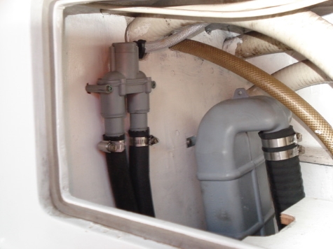
Cheers-Roger.May 14, 2017 at 05:43 #26075ModeratorKeymasterRoger provided some more photos to illustrate his points.


 May 19, 2017 at 10:16 #26080Ronar MParticipant
Hi All
Like Roger I have now fitted a vetus system to Ronar M. The worst bit of the job was removing the old system. Also on the port side of the engine is a large calorifier which made it something of a squeeze to get the waterlock in. I bolted a piece of marine ply to the rear of the engine bearer and screwed the waterlock to that but had to re-route the sea water intake over the top of the gearbox before joining it back to its original route along the port side of the engine.
Cheers, TrevorMay 19, 2017 at 13:08 #26081ParticipantHi Trevor,
Glad to hear all went well. However, tell me, where does the air vent return hose re-enter the system. I’ve looked and can see no signs of it. Again much of the system is now ‘boxed in’.
Also as I have a holding tank coupled up to the after head in that space over the port side fuel tank only had so much space for the gooseneck.
(By the way – my earlier post read Peter -it should have been Trevor – sorry, put it down to a senior moment!)-RJuly 7, 2017 at 08:55 #26095Ronar MParticipantHi
Sorry. I haven’t visited this site for a few weeks. In answer to your question about the return hose ……When working on this with Ronar M, I purchased a new fitting to bolt onto the exhaust manifold outlet. The fitting had a threaded hole to take the coolant pipe coming from the air vent. However, though bought to fit the Perkins 4107 engine, it did not. Luckily the shipyard I was working in had a few old Perkins spares and I was able to buy the correct fitting second hand. This was bolted directly to the exhaust manifold outlet and the water injected straight into it. This is the route: the water comes from the sea, through the gearbox (to cool it), then through the heat exchanger (to cool the engine) then up to the air vent in the side locker and finally down again into the exhaust fitting just described. From there it follows the rubber exhaust pipe into the waterlock, then through the gooseneck and so out to the transom. Hope this helps. In Roger’s pictures it is the smaller black tube going into the squarish brass fitting
Cheers, Trevor -
AuthorPosts
- You must be logged in to reply to this topic.